


MCP2515 CAN Bus Module TJA1050 SPI Interface for Arduino UNO Mega MCU

$8.60 Inc. GST
You save
- Description
- Code Examples
- Additional information
- Reviews (0)
Description
📡 MCP2515 CAN Bus Controller Module with TJA1050 Transceiver – SPI Interface | AuscomTech
The MCP2515 CAN Bus Module is a reliable and widely used solution for adding CAN (Controller Area Network) communication to microcontroller projects.
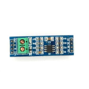
Featuring the MCP2515 CAN controller and TJA1050 CAN transceiver, this module enables stable, high-speed CAN communication via SPI, making it ideal for Arduino, MCU, automotive, industrial, and IoT applications.
With support for CAN V2.0B, a built-in 120Ω termination resistor, and proven compatibility with popular development boards, this module is a must-have for anyone working with CAN-based systems.
⭐ Key Features
🚌 Full CAN Bus Support
Supports CAN V2.0B protocol including standard frames, extended frames, and remote frames.
⚡ High-Speed Communication
Data transfer rates up to 1 Mb/s, suitable for automotive and industrial networks.
🔌 SPI Interface
Simple and reliable SPI connection to microcontrollers.
🧠 Proven Chipset Combination
• MCP2515 – Standalone CAN controller
• TJA1050 – High-speed CAN transceiver for robust signal transmission
🔧 Built-In 120Ω Termination Resistor
Improves signal integrity and reduces noise on longer CAN bus lines.
📏 Compact & DIY-Friendly
Small footprint for easy integration into prototypes and finished projects.
📊 Technical Specifications
| Specification | Details |
|---|---|
| CAN Controller | MCP2515 |
| CAN Transceiver | TJA1050 |
| Protocol | CAN V2.0B |
| Interface | SPI |
| Communication Speed | Up to 1 Mb/s |
| Data Length | 0–8 bytes |
| Frame Types | Standard, Extended, Remote |
| Operating Voltage | 5V DC |
| Termination | Onboard 120Ω resistor |
| Dimensions | ~44 × 28 mm |
🧩 Compatible With
• Arduino Uno
• Arduino Mega 2560
• Arduino Nano
• 51 MCU
• STM32 microcontrollers
• ESP32 / ESP8266 (with level shifting if required)
• Other SPI-capable MCUs
⚙️ Typical Applications
🚗 Automotive diagnostics & ECU communication
🏭 Industrial automation & robotics
📡 CAN-based sensor networks
🏠 Smart home & IoT projects
🎓 Learning CAN bus communication
🔧 Embedded system prototyping
📦 Package Includes
• 1 × MCP2515 CAN Bus Module with TJA1050 Transceiver
📌 Code Examples – MCP2515 CAN Bus Module (TJA1050, SPI)
📋 Overview
This module combines:
-
MCP2515 – CAN controller (SPI interface)
-
TJA1050 – CAN transceiver (physical layer)
It lets an Arduino / MCU talk on a CAN bus, commonly used in:
-
Automotive (ECU, sensors, dashboards)
-
Industrial equipment
-
Robotics and distributed control networks
🔌 Basic Wiring (Arduino UNO)
MCP2515 → Arduino UNO:
| MCP2515 Pin | Arduino UNO Pin |
|---|---|
| VCC | 5V |
| GND | GND |
| SCK | D13 |
| SI (MOSI) | D11 |
| SO (MISO) | D12 |
| CS (NSS) | D10 (configurable) |
| INT | D2 (optional but recommended) |
CAN Bus Side:
| TJA1050 Pin | Connect To |
|---|---|
| CANH | CAN High (twisted pair) |
| CANL | CAN Low (twisted pair) |
For testing, you typically use two MCP2515 modules and connect CANH↔CANH, CANL↔CANL, with a 120 Ω termination resistor at each end of the bus.
📦 Library Required
In Arduino IDE, install:
-
mcp_can library (often listed as “MCP_CAN by Cory J. Fowler”)
🧪 Example 1 – Simple Transmit (Arduino UNO)
This sends a basic CAN frame repeatedly.
🧪 Example 2 – Simple Receive (Arduino UNO)
Use this on a second Arduino + MCP2515 connected to the same CAN bus.
🔁 Two-Node Test Setup
To demonstrate the module to customers, you can describe a simple test:
-
Node A (Sender): Arduino + MCP2515 running Transmit sketch
-
Node B (Receiver): Arduino + MCP2515 running Receive sketch
-
Connect:
-
CANH ↔ CANH
-
CANL ↔ CANL
-
120 Ω termination resistor at each end of cable
-
-
Power both Arduinos via USB
-
Open Serial Monitor on the receiver board → you’ll see CAN frames arriving from Node A.
This is a nice simple “it really works” example.
⚡ ESP32 Example (SPI Pins)
ESP32 also works great with MCP2515; just adjust SPI pins & CS:
🧠 Tips & Notes
-
Make sure the library bitrate matches the actual CAN bus speed (common values: 125 kbps, 250 kbps, 500 kbps).
-
Most MCP2515 breakout boards use an 8 MHz crystal – hence
MCP_8MHZin the init. -
Always use twisted pair for CANH/CANL and terminate the bus with 120 Ω at both ends.
-
You can connect to real automotive CAN with proper voltage and wiring precautions, but always respect vehicle safety and warranty considerations.
Additional information
| Weight | 45 g |
|---|---|
| Dimensions | 260 × 160 × 20 mm |
Only logged in customers who have purchased this product may leave a review.












Reviews
There are no reviews yet.