


PWM Signal Generator Dual Channel 1Hz-150kHz Panel Mount DC 5-24V PWM150

$57.95 Inc. GST
You save
- Description
- Additional information
- Reviews (0)
Description
🔧 PWM150 Dual Channel Panel Mount PWM Signal Generator | AuscomTech
The PWM150 is a panel mount dual-channel PWM signal generator designed for precise square wave and pulse signal generation in electronics testing, control systems, automation and DIY projects. With an adjustable frequency range of 1Hz to 150kHz, independent output channels and fine duty cycle adjustment, it provides flexible signal control in a convenient integrated panel-mounted format.
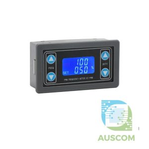
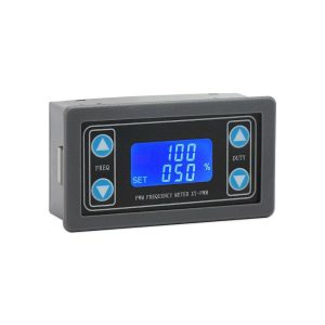
Operating from a DC 5–24V power supply, this digital pulse generator features a rotary encoder, dual LED numerical displays and dedicated control buttons for adjusting frequency, duty cycle and phase. Two independently configurable channels can also operate in synchronised mode for applications requiring coordinated PWM signals.
Ideal for installation in custom control panels, electronics test benches, automation enclosures and equipment prototypes, the PWM150 provides a practical standalone alternative to microcontroller-based signal generation where direct manual adjustment is preferred.
⭐ Key Features
- Panel Mount Design – Integrated front-panel control unit suitable for installation in project enclosures, equipment panels and custom electronics control systems.
- Dual Independent PWM Outputs – Two configurable signal channels (CH1 and CH2) for separate frequency and duty cycle settings.
- Wide Frequency Adjustment – Generate square wave and pulse signals from 1Hz to 150kHz for timing, switching and electronic testing applications.
- Precise Duty Cycle Control – Adjustable from 0.0% to 100.0% in fine 0.1% increments.
- Phase Adjustment – Supports 0° to 360° phase adjustment in 1° steps with synchronisation functionality.
- Dual Channel Synchronisation – Dedicated SYNC function supports linked frequency, duty cycle and phase parameter adjustment.
- Digital Dual LED Display – Green four-digit frequency display and white three-digit duty cycle or phase display for convenient monitoring.
- Rotary Encoder Control – Turn to adjust values and press to select individual digits for precise parameter changes.
- Dedicated Function Buttons – MOD, SET, SYNC and OUT controls allow quick access to channel selection, settings, synchronisation and signal activation.
- One-Touch Output Control – Start or stop PWM generation without switching off the device power supply.
- Parameter Save and Recall – Supports configuration storage and retrieval through the settings menu.
- Configurable Startup Settings – Includes power-on output behaviour and adjustable frequency and duty cycle limits.
- Fast Signal Rise Time – Specified 20ns rise time for sharp pulse transitions.
- Channel Status Indicators – Colour-coded LEDs identify the selected channel and active signal output.
- Standalone Operation – Adjust signals directly from the front panel without additional software, firmware programming or a connected computer.
📊 Technical Specifications
- Model: PWM150
- Product Type: Digital PWM pulse / square wave signal generator
- Mounting Style: Panel mount
- Supply Voltage: DC 5–24V
- Number of Channels: 2 (CH1 / CH2)
- Frequency Range: 1Hz–150kHz
- Default Frequency: 10kHz
- Duty Cycle: 0.0–100.0%
- Duty Cycle Adjustment: 0.1% steps
- Default Duty Cycle: 50%
- Phase Range: 0–360°
- Phase Resolution: 1°
- Maximum Specified Output Current: 0.2A
- Rise Time: 20ns (specified)
- Display: 4-digit green LED + 3-digit white LED
- Input Controls: Rotary encoder and four function buttons
- Operating Functions: Independent channels, synchronisation, adjustable PWM output
- Status LEDs: CH1 (orange), CH2 (blue), OUT (green)
- Dimensions: 120 × 80 × 25mm
- Power Requirement: External DC supply
📈 Frequency Accuracy
- 1Hz–10kHz: 0.2% specified accuracy
- 10kHz–50kHz: 0.4% specified accuracy
- 50kHz–150kHz: 2% specified accuracy
🎛️ Control Functions
- Rotary Encoder: Rotate to increase or decrease the selected parameter. Press to select individual digits for fine adjustment.
- MOD Button: Switch between CH1 and CH2 parameter settings or view duty cycle and phase in synchronisation mode.
- SET Button: Access system settings including power-on output configuration, parameter save/recall and adjustment limits.
- SYNC Button: Enable linked control of channel parameters for synchronised operation.
- OUT Button: Enable or disable signal generation with one button press.
- Frequency Display: Upper green LED readout indicates the selected frequency.
- Duty / Phase Display: Lower white LED readout shows duty cycle percentage or phase angle according to the selected mode.
🧩 Typical Applications
- Panel-mounted frequency and PWM control systems
- Custom electronics testing equipment
- Laboratory signal generation and circuit experiments
- Square wave and pulse input simulation
- Motor speed controller PWM input testing
- LED dimming driver signal testing
- Embedded systems and digital logic development
- Arduino, ESP32 and STM32 input testing with appropriate voltage interfacing
- Industrial automation prototypes and control panel projects
- Frequency and duty cycle testing
- Phase synchronisation experiments
- DIY electronic instrument and enclosure builds
⚠️ Important Notes
- Panel Installation: Designed for panel mounting. Verify enclosure clearance and required cut-out dimensions before installation. The specified dimensions are overall product dimensions, not panel cut-out measurements.
- External Power Supply Required: Requires DC 5–24V input. Power supply is not included.
- Low-Current Signal Output: This product generates PWM control signals and is not a high-power motor driver or variable DC power supply.
- Output Current: Maximum specified current is 0.2A. Use a suitable external MOSFET or driver circuit for higher-current loads.
- Logic Voltage Compatibility: Verify signal output voltage before connecting to 3.3V or 5V microcontroller inputs. Use level shifting or suitable signal conditioning where required.
- Output Voltage: The DC 5–24V specification refers to the stated supply range. A separate regulated output voltage specification is not provided.
- Synchronisation: Phase adjustment and linked control are supported through the device synchronisation function.
- Frequency Accuracy: Specified accuracy varies with output frequency.
- Installation: Confirm power polarity, electrical connections and connected equipment ratings before operation.
📦 Package Includes
- 1 × PWM150 Dual Channel Panel Mount PWM Signal Generator
🔗 Recommended Accessories (Not Included)
- DC 5–24V Power Supply – Suitable external supply for powering the generator.
- Oscilloscope – Measure output waveform, frequency, duty cycle and phase relationships.
- MOSFET Driver Module – Interface PWM control signals with suitable higher-current loads.
- Logic Level Converter – Connect signal outputs to voltage-sensitive Arduino, ESP32 and other microcontroller inputs where required.
Additional information
| Weight | 160 g |
|---|---|
| Dimensions | 260 × 160 × 50 mm |
Only logged in customers who have purchased this product may leave a review.






Reviews
There are no reviews yet.