


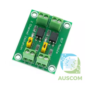
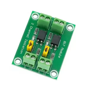


PC817 2 Channel Optocoupler Isolation Module 3.6–30V Level Converter

$7.99 Inc. GST
You save
- Description
- Code Examples
- Additional information
- Reviews (0)
Description
🔌 PC817 2-Channel Optocoupler Isolation Module – 3.6–30V Signal Isolation Board | AuscomTech
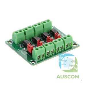
The PC817 2-Channel Optocoupler Isolation Board is designed to provide safe, reliable electrical isolation between low-voltage control logic and higher-voltage circuits. Using PC817 photoelectric optocouplers, this module protects sensitive microcontrollers from voltage spikes, noise, and ground loops while enabling clean signal transfer.
It is ideal for Arduino, ESP32, Raspberry Pi, PLCs, and industrial control systems, allowing 3.3V or 5V logic signals to interface safely with 3.6–30V control circuits.
⭐ Key Features
🔒 Photoelectric Isolation (PC817)
Provides galvanic isolation between input and output, protecting MCUs from high-voltage interference.
🔁 2 Independent Channels
Two fully isolated signal channels allow simultaneous control or sensing.
⚡ Wide Voltage Compatibility
Supports control signals from 3.6V to 30V, ideal for 12V and 24V systems.
🧠 Logic-Level Friendly
Compatible with 3.3V and 5V logic from Arduino, ESP32, STM32, Raspberry Pi, and PLCs.
🔧 Configurable Output Logic
Jumper-selectable high-level or low-level output, adapting easily to different control requirements.
📉 Noise & Ground Loop Protection
Excellent for noisy environments, long cable runs, and mixed-voltage systems.
📊 Technical Specifications
| Specification | Details |
|---|---|
| Optocoupler | PC817 |
| Channels | 2 |
| Input Signal Voltage | 3.6V – 24V |
| Output Voltage Range | 3.6V – 30V |
| Max Output Current | 10mA |
| Signal Frequency | ≤ 4kHz |
| Output Logic | High / Low (jumper selectable) |
| Isolation Method | Photoelectric |
| Dimensions | 37 × 30 × 10 mm |
⚠️ Note: Voltage and output current are inversely proportional. Not suitable for high-speed pulse signals above 4kHz due to PC817 switching limitations.
🧩 Compatible With
• Arduino (Uno, Mega, Nano)
• ESP32 / ESP8266
• Raspberry Pi (GPIO isolation)
• STM32 microcontrollers
• PLC digital inputs
• Relay & MOSFET driver circuits
⚙️ Typical Applications
• MCU to high-voltage signal isolation
• 3.3V / 5V to 12V / 24V level shifting
• Relay, MOSFET, and transistor driving
• Industrial sensor & actuator interfacing
• Noise suppression and EMI protection
• Ground loop isolation
• Automation and control systems
📦 Package Includes
• 1 × PC817 2-Channel Optocoupler Isolation Module
📌 Code Examples & Usage – PC817 2-Channel Optocoupler Isolation Board
📋 What This Module Is For
The PC817 optocoupler isolation board uses two PC817 optocouplers to provide electrical isolation between:
👉 A noisy, high-voltage, or untrusted circuit
and
👉 A sensitive microcontroller (Arduino / ESP32 / Raspberry Pi)
It’s ideal for:
✔ Protecting MCU GPIOs from voltage spikes
✔ Reading high-voltage signals (e.g., mains, 12 V logic)
✔ Isolating relay triggers or motor drivers
✔ Reducing noise and ground loops
🔌 How It Works
Each channel uses an LED + phototransistor inside the PC817:
-
Input side (LED): Driven by the signal you want to monitor
-
Output side (phototransistor): Provides a clean digital signal to your MCU
Because the LED and transistor are optically coupled, there’s no direct electrical connection — giving true galvanic isolation.
📌 Wiring (Typical)
Isolated Input Side
| Module Input | Connect To |
|---|---|
| IN1 / IN2 | Signal to be monitored (e.g., from 5 V / 12 V / mains interface) |
| GND (Input) | Signal ground or reference |
| VCC (Input) | Suitable LED drive voltage (depends on your input — usually 5 V) |
Output Side (MCU Side)
| Module Output | Connect To |
|---|---|
| OUT1 / OUT2 | Arduino / ESP32 digital pin (e.g., D2) |
| GND (Output) | MCU ground |
| VCC (Output) | MCU logic voltage (3.3 V or 5 V) |
🔌 The Input side and Output side grounds are not connected — that’s the whole point of isolation.
🧪 Arduino Example — Reading an Isolated Digital Signal
This example assumes:
-
IN1 receives a digital signal (e.g., 5 V logic)
-
OUT1 goes to Arduino D2
-
Output logic is pulled up to Arduino 5 V
Note: The PC817 output transistor typically pulls the output LOW when active. If your wiring differs, invert the logic accordingly.
⚡ ESP32 Example — Safe Isolation Reading
This example assumes the output side is pulled up to 3.3 V for ESP32 logic.
🧠 Typical Use Cases
🔹 High-Voltage Safeguard
Use the input side to monitor a high-voltage logic line (e.g., 12 V from a relay board), and let the optocoupler protect your low-voltage microcontroller.
🔹 Motor Driver Isolation
Read a tachometer or limit switch on a noisy motor driver without picking up spikes.
📊 Pull-Up Considerations
Optocouplers output via a transistor — they sink current, but do not source it.
So typically you will:
✔ Use INPUT_PULLUP on the MCU pin
✔ Or add an external pull-up resistor (10 kΩ) to 3.3 V / 5 V
🔌 Example: Isolated Button Input
This lets you keep a noisy button/switch isolated from your MCU:
🧠 Notes & Tips
✔ Remember: Two isolated grounds — don’t connect them directly
✔ Input LED current for the PC817 should be limited (e.g., via resistor)
✔ Typical CTR (current transfer ratio) means low input LED current gives detectable output
✔ The PC817 handles up to 30 V on the isolated input safely (as long as currents are controlled)
Additional information
| Weight | 40 g |
|---|---|
| Dimensions | 260 × 160 × 20 mm |
Only logged in customers who have purchased this product may leave a review.












Reviews
There are no reviews yet.