


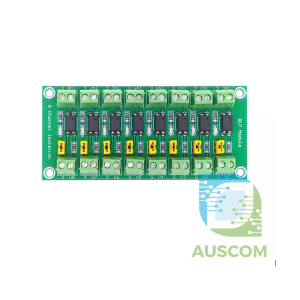
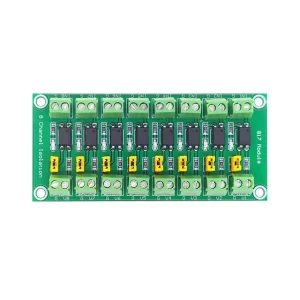


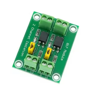
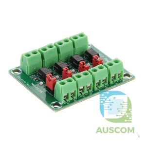
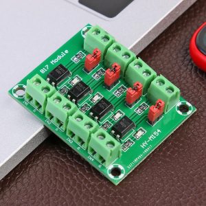
PC817 8 Channel Optocoupler Isolation Module 3.3–30V Signal Converter

$13.35 Inc. GST
You save
- Description
- Code Examples
- Additional information
- Reviews (0)
Description
🔌 PC817 8-Channel Optocoupler Isolation Module – 3.3V to 30V Signal Voltage Converter | AuscomTech
The PC817 8-Channel Optocoupler Isolation Board is a compact, high-density solution for signal isolation and voltage level conversion between low-voltage logic systems and higher-voltage control circuits.
Using PC817 optoelectronic isolators, this module protects sensitive controllers from noise, voltage spikes, and ground loops while enabling safe and reliable multi-channel control.
It is ideally suited for Arduino, ESP32, Raspberry Pi, PLCs, and industrial automation systems where multiple isolated signals are required in a small footprint.
⭐ Key Features
🔢 8 Independent Optocoupler Channels
Each channel uses a dedicated PC817 optocoupler for full electrical isolation.
⚡ Wide Voltage Compatibility
Supports 3.3V / 5V logic inputs and switches output voltages from 3.3V up to 30V DC.
🔒 Strong Electrical Isolation
Photoelectric isolation effectively blocks electrical noise, transients, and ground loops.
🔧 Configurable Output Logic
Onboard jumper allows selection of active-high or active-low output, adapting easily to different control requirements.
🧠 MCU & PLC Friendly
Compatible with Arduino, ESP32, ESP8266, STM32, Raspberry Pi GPIO, and PLC digital outputs.
📦 Compact Multi-Channel Design
Ideal for projects requiring multiple isolated signals without multiple single-channel boards.
📊 Technical Specifications
| Specification | Details |
|---|---|
| Optocoupler | PC817 |
| Channels | 8 |
| Input Signal Voltage (Drive Side) | 3.3V – 24V DC |
| Output Voltage Range | 3.3V – 30V DC |
| Max Output Current | 10mA per channel |
| Output Logic | Jumper selectable (Active High / Active Low) |
| Isolation Type | Photoelectric (Optocoupler) |
| Signal Frequency | ≤ 3kHz |
⚠️ Important Notes
• Output current is limited to 10mA per channel (voltage and current are inversely related).
• Not suitable for high-speed signals or PWM above ~3kHz. For faster switching, use a high-speed optocoupler.
🧩 Compatible With
• Arduino (Uno, Mega, Nano)
• ESP32 / ESP8266
• Raspberry Pi GPIO
• STM32 microcontrollers
• PLC digital I/O
• Relay, MOSFET, and transistor driver stages
⚙️ Typical Applications
• PLC signal interfacing
• Microcontroller input/output isolation
• 3.3V / 5V to 12V / 24V level shifting
• Industrial automation systems
• Relay, MOSFET, and transistor control
• Noise-sensitive or mixed-voltage circuits
• Ground loop and interference protection
📦 Package Includes
• 1 × PC817 8-Channel Optocoupler Isolation Module
📌 Code Examples & Usage – PC817 8-Channel Optocoupler Isolation Board
📋 What This Module Is For
The PC817 8-Channel Optocoupler Isolation Board uses eight PC817 optocouplers to safely isolate up to eight input signals from your microcontroller.
It is great for:
✔ Monitoring high-voltage logic safely
✔ Isolating noisy signals
✔ Protecting microcontroller GPIOs from voltage spikes
✔ Reading multiple isolated inputs (e.g., sensors, switches, relays)
Each channel provides galvanic isolation between:
🔹 The input (external/high-voltage) side
and
🔹 The output (MCU) side
🔌 How It Works (All 8 Channels)
Each channel contains:
➡ An LED (input side)
➡ A phototransistor (output side)
When the LED is illuminated by the input signal, the phototransistor conducts on the MCU side — without any electrical connection between the two sides.
This protects your MCU from voltage spikes, ground loops, and noise from industrial circuits, motor drivers, etc.
📌 Wiring (Typical)
Input Side (Isolated side)
| Module Label | Connect To |
|---|---|
| IN1–IN8 | Signals from external system (e.g., 5–30 V logic) |
| GND (Input) | External system ground |
| VCC (Input) | External supply voltage for LED side (5–30 V) |
Output Side (MCU side)
| Module Label | Connect To |
|---|---|
| OUT1–OUT8 | GPIO pins on MCU (Arduino/ESP32/etc.) |
| GND (Output) | MCU ground |
| VCC (Output) | MCU logic voltage (3.3 V or 5 V) |
🔌 The input ground and output ground must be kept separate — that’s what isolation does!
🧪 Arduino Example — Reading Multiple Isolated Inputs
This example reads 8 isolated inputs on Arduino:
Note:
Because the PC817 output transistor sinks to ground, outputs are typically LOW when active — so we use INPUT_PULLUP on the MCU side so the default state is HIGH until triggered.
⚡ ESP32 Example — 8 Channel Isolation
This example reads all 8 channels on ESP32 (use 3.3 V logic).
🧠 Typical Use Cases
🛑 High-Voltage Logic Safeguard
If you’re monitoring signals from 12 V systems, industrial PLCs, motor controllers, etc., this module protects your MCU against voltage spikes.
🔁 Motor Control / Sensor Feedback
Isolate encoder/limit sensor signals from high-noise environments.
🔄 Multi-Input Control Panel
Use with buttons, switches, and control panels where isolation is recommended.
📊 Pull-Up Strategy
The PC817 output is a phototransistor that pulls the MCU input LOW when active. Therefore:
✔ Use INPUT_PULLUP on your MCU
or
✔ Add an external pull-up resistor (e.g., 10 kΩ) to your MCU’s logic voltage (3.3 V or 5 V)
🧠 Isolation Notes
✔ Input and Output circuits are not connected — no shared ground
✔ If you do want a shared reference, consider adding an isolated power supply
✔ This board works for DC signals only (for AC logic you will need additional circuitry)
Additional information
| Weight | 60 g |
|---|---|
| Dimensions | 260 × 160 × 20 mm |
Only logged in customers who have purchased this product may leave a review.












Reviews
There are no reviews yet.