
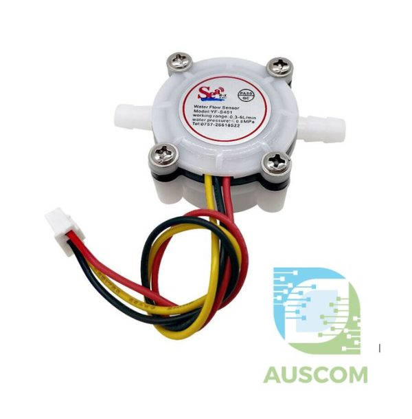
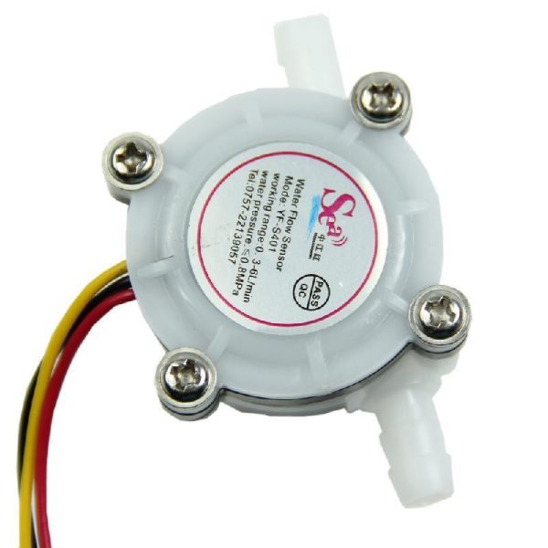
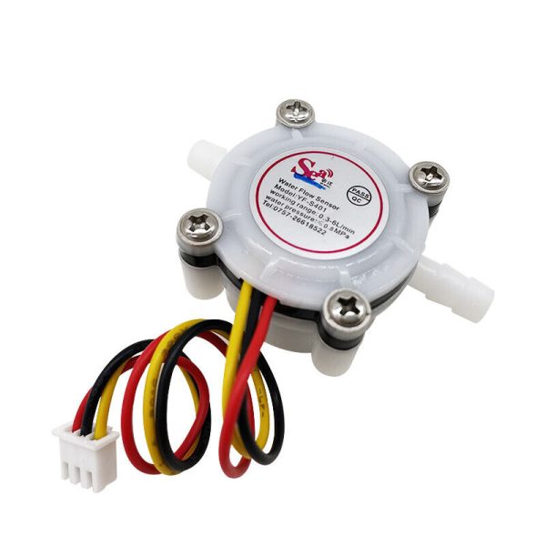
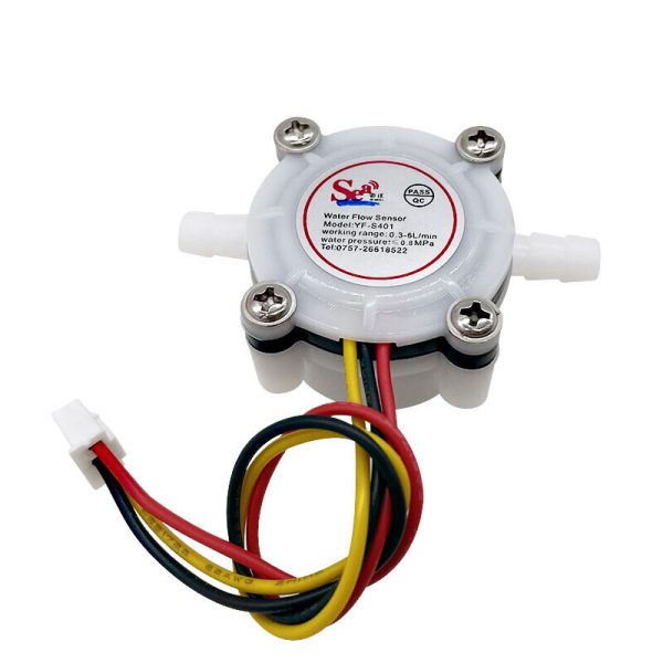
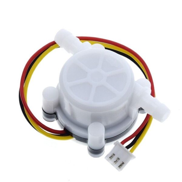
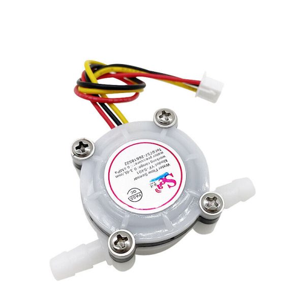
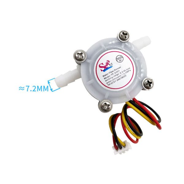
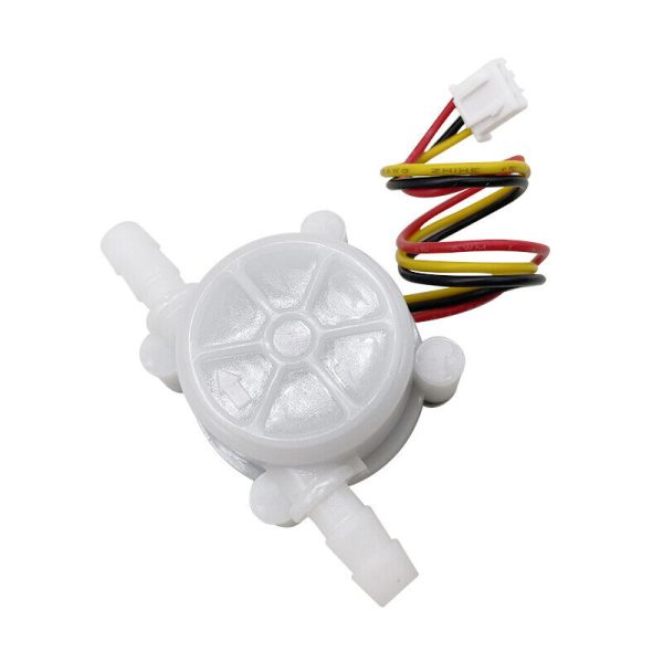
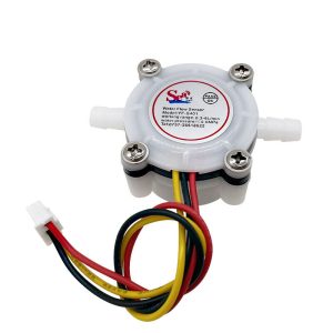
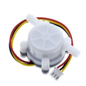
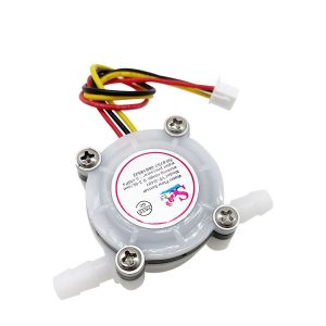
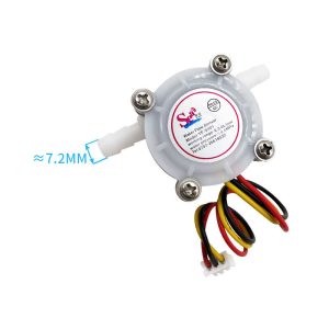
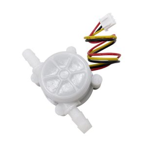
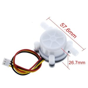
YF-S401 Water Flow Sensor Hall Effect 0.1–5L/min Leakproof
$15.95 Inc. GST
You save
- Description
- Code Examples
- Additional information
- Reviews (0)
Description
🌊 YF-S401 Water Flow Sensor Hall Effect 0.1–5L/min Leakproof | AuscomTech
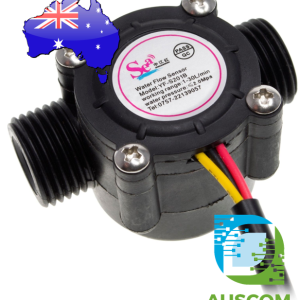
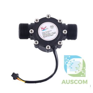
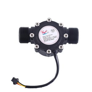
The YF-S401 Water Flow Sensor is a compact, high-precision hall-effect flow sensor designed for accurate low-flow water measurement in appliances and automation systems.
Built with a durable PVC body, stainless steel shaft, and high-quality hall sensor, the YF-S401 produces a stable pulse output proportional to flow rate. It is widely used in coffee machines, water dispensers, heaters, and embedded control systems where reliable, repeatable water flow detection is required.
⭐ Key Features
🧲 Hall Effect Flow Sensing
High-quality hall sensor delivers stable pulse output for accurate flow measurement.
📏 Low Flow Measurement Range
Designed for precise monitoring of small flows from 0.1 to 5 L/min.
🧱 Durable & Leakproof Construction
PVC housing with high-sealing performance and internal sealing ring for long-term reliability.
⚙️ Stainless Steel Shaft
Abrasion-resistant axis improves durability and extends service life.
🔌 Wide Operating Voltage
Operates from DC 5–24V, suitable for both low-voltage electronics and control systems.
🌱 RoHS Compliant Materials
Manufactured with environmentally friendly, compliant materials.
📊 Technical Specifications
Model: YF-S401
Sensor Type: Hall effect water flow sensor
Operating Voltage: DC 5–24V (min. 4.5V)
Max Current: ≤15mA @ DC 5V
Load Capacity: ≤10mA @ DC 5V
Flow Range: 0.1–5 L/min
Accuracy: ±2%
Pulse Output Duty Cycle: 50% ±10%
Pulse Output High Level: >4.7V (at 5V supply)
Flow Pulse Formula: F = (98 × Q) ±2% (Q = L/min)
Internal Diameter: 1.2 mm
Water Resistance (Static): 0.35 MPa
Max Water Pressure: ≤0.8 MPa
Operating Temperature: ≤80°C
Liquid Temperature: ≤120°C
Operating Humidity: 35%–90% RH
Storage Temperature: −25°C to +80°C
Storage Humidity: 25%–95% RH
Insulation Resistance: >100 MΩ
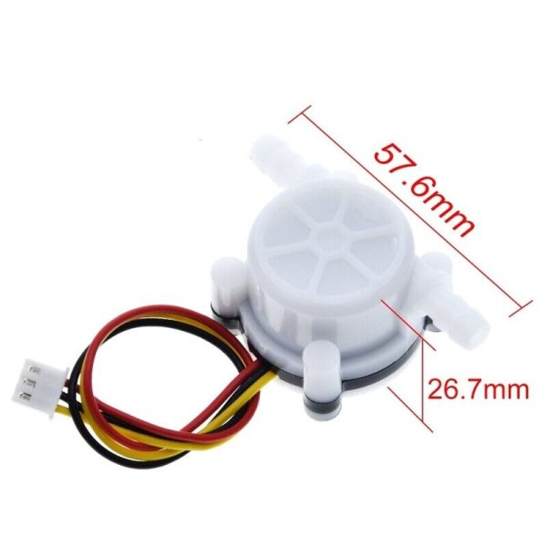
Dimensions: 58 × 35 × 27 mm
Weight: Approx. 25 g
⚠️ Important Notes
• Install vertically with an inclination ≤5°
• Ensure liquid temperature does not exceed 120°C
• Avoid strong vibration, shock, or corrosive chemicals
• Pulse output requires frequency measurement in software
🧩 Compatible With
• Arduino (Uno, Nano, Mega)
• ESP32 / ESP8266
• STM32 microcontrollers
• PLC digital input modules
• Coffee machines and water dispensers
• Embedded control systems
⚙️ Typical Applications
• Coffee machines
• Water dispensers
• Water heaters
• Low-flow water monitoring
• Automation and control systems
• Embedded electronics projects
🔌 Wiring Reference
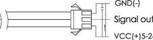
• Red: VCC (Positive)
• Yellow: Pulse Signal Output
• Black: GND (Negative)
📦 Package Includes
• 1 × YF-S401 Water Flow Sensor
📌 Code Examples – SEA YF-S401 Hall Effect Flowmeter (0.3 – 6 L/min)
📋 Overview
This SEA YF-S401 liquid flow sensor outputs a pulse train whose frequency is proportional to the flow rate. It’s ideal for:
-
Small pumps & dispensing systems
-
Aquarium / hydroponics
-
Coffee machines & beverage dosing
-
Precision fluid measurement
-
IoT flow monitoring
Typical specs:
-
Flow range: 0.3–6 L/min
-
Hall effect pulse output (digital)
-
Works with 3.3 V – 24 V systems
-
Easy to interface with microcontrollers
⚠ Wiring Notes
| Pin | Function |
|---|---|
| Red | Power supply (3.3–24 V DC) |
| Black | Ground (common with MCU) |
| Yellow | Pulse output (open-collector) |
Important:
-
The yellow output is an open-collector / open-drain signal.
-
You must use a pull-up resistor (typically 4.7 kΩ to the MCU logic voltage) between the pulse pin and MCU Vcc.
-
Ensure common ground between sensor and MCU.
📈 Basic Flow Equation
The sensor produces pulses proportional to flow:
Where K is the calibration constant. For the YF-S401, this is typically around:
➡ A calibration value may vary slightly based on your sensor lot — best confirmed with a calibration run.
🧪 1️⃣ Arduino Example – Flow Rate & Total Volume
Use an interrupt pin for accurate pulse counting (e.g., pin 2 on UNO).
⚡ 2️⃣ ESP32 Example – Low Flow Precision
ESP32 often uses custom pins — choose ANY interrupt-capable GPIO.
🧠 Notes & Calibration
✔ Choosing a precise Kfactor is critical for accurate measurement — use calibration with a known volume for best results.
✔ For low flow rates (<1 L/min), sample over longer intervals (e.g., 2–5 seconds) to smooth noise.
✔ Use INPUT_PULLUP or an external pull-up resistor between the pulse pin and the MCU Vcc.
📊 Flow Smoothing & Filtering
You can improve measurement stability by averaging over multiple intervals:
🔌 Pump / Control Example (Optional)
Use the flow meter as a closed-loop control:
Make sure your pump is driven properly (use a relay/driver) — do not drive it directly from an MCU pin.
💡 Tips & Troubleshooting
✔ Add a small capacitor (100 nF) across sensor power for noise suppression.
✔ Shielded cable improves signal in industrial environments.
✔ Verify the pulse shape with an oscilloscope if readings jump around.
✔ Long wiring runs may require a pull-up of lower resistance (e.g., 2.2 kΩ) for cleaner edges.
Additional information
| Weight | 100 g |
|---|---|
| Dimensions | 260 × 160 × 20 mm |
Only logged in customers who have purchased this product may leave a review.













Reviews
There are no reviews yet.