


YF-B8 1/2″ Brass Water Flow Sensor Hall Effect Pulse Flowmeter 5–18V Arduino

$78.00 Inc. GST
You save
- Description
- Code Examples
- Additional information
- Reviews (0)
Description
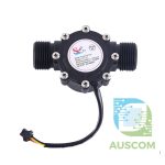
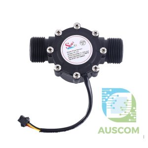
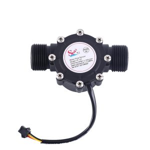
💧 YF-B8 1/2″ Brass Water Flow Sensor – Hall Effect Pulse Turbine Flowmeter DC 5–18V
Overview
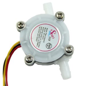
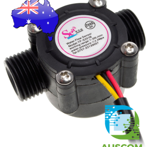
The YF-B8 Water Flow Sensor is a durable and high-precision 1/2″ (DN15) brass turbine flowmeter with an integrated Hall effect sensor.
It accurately measures the rate of water flow and outputs a corresponding pulse signal, which can be read by Arduino, ESP32, Raspberry Pi, PLCs, and other microcontrollers for water monitoring, automation, and flow control systems.
Built with a solid brass valve body, this sensor offers excellent durability and corrosion resistance, while the Hall sensor ensures stable and accurate readings across a wide voltage range.
⚙️ Key Features
-
🔹 High-quality brass construction – corrosion-resistant and durable
-
🔹 Hall-effect pulse output for precise flow measurement
-
🔹 Linear response between pulse frequency and water flow rate
-
🔹 Wide voltage range: operates from DC 5 V to 18 V
-
🔹 Supports flow measurement up to 30 L/min
-
🔹 Compact 1/2″ BSP thread design for easy installation
-
🔹 Compatible with Arduino, ESP32, Raspberry Pi, and PLC systems
-
🔹 Ideal for smart water management, automation, and IoT applications
📊 Specifications
| Parameter | Description |
|---|---|
| Model | YF-B8 |
| Type | Hall Effect Water Flow Sensor |
| Thread Size | 1/2″ BSP (DN15) |
| Material | Brass |
| Working Voltage | DC 5–18 V |
| Output Type | NPN Pulse Signal |
| Flow Range | 1 – 30 L/min ±3% |
| Pressure Resistance | ≤ 1.75 MPa |
| Operating Temperature | −20 °C to +100 °C |
| Output Pulse High Level | > 4.5 V (at 5 V input) |
| Output Pulse Low Level | < 0.5 V |
| Flow Pulse Formula | F = (6.6 × Q) ±5% (Q = L/min) |
| Tightness Test | 1.7 MPa water pressure for 1 min, no leakage/deformation |
| Output Resistance | 100 MΩ |
| Weight | Approx. 100 g |
| Medium Compatibility | Water and non-corrosive liquids |
🧩 Applications
✅ Water heater and dispenser flow monitoring
✅ Smart irrigation systems
✅ Water purification and filtration systems
✅ Industrial flow measurement and automation
✅ Arduino and ESP32 IoT data logging projects
✅ Home water usage tracking and control
📦 Package Includes
-
1 × YF-B8 1/2″ Brass Water Flow Sensor
⚠ Electrical & Safety Notes
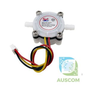
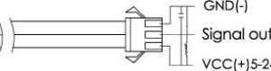
This sensor has 3 wires:
-
Red – VCC (5–18V)
-
Black – GND
-
Yellow – Pulse output (Hall-effect)
For Arduino / ESP32 use, the safest option is:
-
Power the sensor from 5V
-
Connect the yellow wire to a digital input pin (with pull-up)
-
Never exceed the MCU input voltage (5V on Arduino, 3.3V on ESP32)
If you want to power the sensor from 12V (e.g. in a pump system), you must not feed 12V directly into the microcontroller pin. Use one of these approaches:
-
Use a 5V regulator/buck module to supply the sensor with 5V, and wire it directly to the Arduino/ESP32.
-
Use an opto-isolated input / level-shifter module so the yellow wire is isolated from the microcontroller pin.
This protects the microcontroller and is strongly recommended for anything tied into real-world plumbing or pumps.
🔌 Basic Arduino Wiring
-
Sensor Red → 5V
-
Sensor Black → GND
-
Sensor Yellow → D2 (interrupt-capable pin on Arduino Uno)
Make sure GND of the sensor and Arduino are connected together.
📏 Flow Calculation
For this type of brass YF-series sensor the pulse frequency is typically:
Frequency (Hz) ≈ 11 × Flow (L/min)
So:
-
Flow (L/min) = PulsesPerSecond / 11
We use that in the code below.
🧪 Arduino Example: Display Flow Rate & Total Litres
This example:
-
Uses an interrupt on pin 2 to count pulses
-
Calculates L/min and total litres every second
-
Prints the results to the Serial Monitor
⚡ ESP32 Example (3.3V Logic)
For ESP32 you should still power the sensor at 5V, but the signal must be kept within 3.3V logic. Two safe options:
-
Use a 3.3V–5V level-shifter / optocoupler module on the yellow wire
-
Use an external pull-up to 3.3V on the ESP32 pin and ensure the sensor output is open-collector (typical for these sensors)
Example assuming you’ve made the signal safe for 3.3V and wired yellow to GPIO 23:
✅ Recommended Extra Modules (for safety & reliability)
To make this sensor easier and safer to use in real-world projects, we recommend pairing it with:
-
A 5V buck converter or regulator (if your system runs from 12V)
-
A 4-channel or 8-channel opto-isolated input / level-shifter module for the pulse output
-
A surge-protected power supply if used near pumps/inductive loads
Additional information
| Weight | 150 g |
|---|---|
| Dimensions | 260 × 160 × 40 mm |
Only logged in customers who have purchased this product may leave a review.












Reviews
There are no reviews yet.