




XY-WJ01 Digital Timer Delay Relay Module 6-30V LCD Programmable Cycle Switch

$36.50 Inc. GST
You save
- Description
- Additional information
- Reviews (0)
Description
🔧 XY-WJ01 Digital Programmable Timer Delay Relay Module | AuscomTech
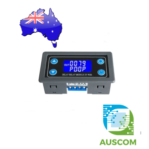
The XY-WJ01 is a multifunction digital timer relay controller designed for precise switching, adjustable delays, repeating cycles and automated electrical control. Featuring a dual-line illuminated LCD display, integrated push-button controls and a protective enclosure, it provides a convenient solution for electronic timing applications.
Operating from a DC 6V–30V power supply, the controller supports 10 programmable operating modes (P0–P9), with timing adjustments from 0.01 seconds up to 9999 minutes depending on the selected timing range. Its relay output can switch compatible AC or DC loads independently of the controller’s power supply.
High-level, low-level and contact-switch triggering allow integration with sensors, external switches and microcontroller systems. A TTL-level UART interface provides additional options for remote parameter configuration and control.
⭐ Key Features
- 10 Programmable Operating Modes: Supports one-shot delays, retriggerable timing, delayed activation, automatic cycling and signal-hold functions.
- Dual-Line LCD Display: Displays timing information, operating status and selected program parameters.
- Wide DC Input Range: Operates from 6V to 30V, suitable for a variety of low-voltage control systems.
- Adjustable Timing: Four selectable time formats provide fine adjustment from hundredths of a second to extended intervals.
- Configurable Trigger Inputs: Accepts high-level, low-level or external contact-switch signals.
- Relay Switching Output: Controls compatible AC or DC electrical loads up to the specified relay ratings.
- Independent Timing Parameters: Configure relay ON time (OP), OFF time (CL) and repeat cycles (LOP).
- UART Communication: Supports serial parameter reading, writing and control commands.
- Pause and Stop Control: Front-panel controls allow timing interruption and manual operation according to the selected mode.
- Non-Volatile Parameter Storage: Configuration settings are retained after the power supply is disconnected.
- Automatic Low-Power Display Mode: Optional LCD backlight shutdown after approximately five minutes of inactivity, with button-operated wake-up.
- Optocoupler-Isolated Trigger Circuit: Provides improved resistance to electrical interference on the trigger input.
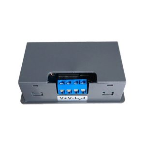
- Enclosed Panel-Style Design: Integrated housing and four control buttons provide convenient installation and operation.
📊 Technical Specifications
- Model: XY-WJ01
- Product Type: Programmable digital timer relay controller
- Supply Voltage: DC 6V–30V
- Relay Channels: 1
- Maximum DC Relay Load: 30V DC, 5A
- Maximum AC Relay Load: 220V AC, 5A
- Timing Range: 0.01 seconds to 9999 minutes, depending on selected format
- Operating Modes: P0–P9 (10 modes)
- High-Level Trigger: 3.0V–24.0V
- Low-Level Trigger: 0V–0.2V
- Additional Trigger: External switch/contact signal
- Serial Interface: TTL-level UART
- UART Configuration: 9600 baud, 8 data bits, 1 stop bit
- Static Current: Approximately 15mA
- Operating Current: Approximately 50mA
- Relay Mechanical Life: More than 100,000 operations (manufacturer-stated)
- Specified Operating Temperature: -40°C to +85°C
- Dimensions: Approximately 80 × 38 × 19mm
- Display: Dual-line backlit LCD
- Controls: SET, UP, DOWN and STOP/PAUSE
- Parameter Memory: Non-volatile storage
- Enclosure Colour: Grey and black
⚙️ Programmable Operating Modes
The controller provides 10 operating modes for different timing and switching requirements.
- P0 – Single Pulse: Trigger activates the relay for the configured OP duration, then switches it OFF. Additional triggers are ignored during timing.
- P1 – Retriggerable Pulse: Trigger activates the relay for the OP duration. Another trigger during operation restarts the timer.
- P2 – Trigger Cancellation: Relay activates for the OP duration. A second trigger during timing resets the timer, switches the relay OFF and stops the timing operation.
- P3 – Delayed Activation: Trigger starts the CL delay with the relay OFF. After the delay expires, the relay switches ON.
- P4 – Triggered ON/OFF Cycling: Relay switches ON for OP, then OFF for CL, repeating for the configured LOP count. The relay remains OFF when cycling finishes.
- P5 – Triggered OFF/ON Cycling: Relay remains OFF for CL, then switches ON for OP, repeating for the configured LOP count. The relay remains ON when cycling finishes.
- P6 – Automatic ON/OFF Cycling: Timing begins automatically after power-on. Relay switches ON for OP, then OFF for CL, repeating according to LOP. External triggers are ignored during cycling, and the relay remains OFF at completion.
- P7 – Automatic OFF/ON Cycling: Timing begins automatically after power-on. Relay remains OFF for CL, then ON for OP, repeating according to LOP. External triggers are ignored during cycling, and the relay remains ON at completion.
- P8 – Signal-Hold Delayed OFF: Relay remains ON while the trigger signal is present. When the signal is removed, the OP countdown begins before switching OFF. A new trigger during the countdown clears the timer.
- P9 – Signal-Hold Delayed ON: Relay remains OFF while the trigger signal is present. When the signal is removed, the CL countdown begins before switching ON. A new trigger during the countdown clears the timer.
⏱️ Timing Parameters and Adjustment
Timing behaviour is controlled through three principal parameters, with separate adjustment where supported by the selected operating mode.
- OP (ON Time): Duration for which the relay remains energised.
- CL (OFF Time): Duration for which the relay remains de-energised.
- LOP (Loop Count): Number of repeated cycles, adjustable from 1 to 9999, with a continuous-loop setting available.
Four timing formats can be selected within the parameter adjustment interface:
- XXXX: 1–9999 seconds, 1-second resolution.
- XXX.X: 0.1–999.9 seconds, 0.1-second resolution.
- XX.XX: 0.01–99.99 seconds, 0.01-second resolution.
- X.X.X.X: 1–9999 minutes, displayed in the module’s minute-based format.
For example, an ON duration of 3.2 seconds can be configured using the 0.1-second format, with the display showing 003.2.
🖥️ Front-Panel Operation
- Enter Settings: Press and hold SET to access the configuration interface.
- Select Operating Mode: Use UP and DOWN to choose P0–P9.
- Configure Parameters: Press SET to advance through available settings and use UP or DOWN to modify values.
- Change Timing Resolution: In the OP/CL adjustment interface, briefly press STOP/PAUSE to change the timing format.
- Save Configuration: Press and hold SET for more than two seconds to save settings and exit.
- View Current Parameters: Briefly press SET during normal operation to inspect the configuration without interrupting operation.
- Display Switching: In P4–P7, briefly press DOWN to switch between runtime and cycle-count information.
- Pause Operation: In P0–P7, the pause button can start or suspend timing. During suspension, the relay switches OFF and the display indicates the paused state.
- Signal Trigger Function: In P8/P9, the pause button acts as a trigger input from the running interface.
🔌 UART Serial Communication
The controller includes a TTL-level UART interface for reading parameters and sending configuration commands from compatible external devices.
This allows integration with Arduino, ESP32, STM32 and other microcontroller platforms when appropriate UART voltage-level compatibility is provided.
- Baud Rate: 9600
- Data Format: 8 data bits, 1 stop bit
- Parity: No parity (8N1)
- read: Read current system parameters.
- OP:xxxx: Set ON time using 1-second resolution.
- OP:xxx.x: Set ON time using 0.1-second resolution.
- OP:xx.xx: Set ON time using 0.01-second resolution.
- CL:xxxx: Set OFF time using 1-second resolution.
- CL:xxx.x: Set OFF time using 0.1-second resolution.
- CL:xx.xx: Set OFF time using 0.01-second resolution.
- LP:xxxx: Configure the number of repeated cycles.
- PX: Select the operating mode, where X represents 0–9.
- start: Trigger/start timing in P0–P7.
- stop: Pause timing in P0–P7.
The manufacturer documentation also specifies minute-based OP/CL command formats. These use decimal-point placement to select the minute timing range.
UART is a control and configuration interface, not a direct USB connection. A suitable USB-to-TTL serial adapter is required when communicating from a computer.
🧩 Typical Applications
- Automatic equipment power cycling
- Delayed motor and fan activation
- Electronic pulse generation and switching
- Timed lighting and indicator control
- Sensor-triggered automation
- Arduino and ESP32 control projects
- Sequential relay switching
- Laboratory testing and electronic experiments
- Repeated ON/OFF operation for pumps and small actuators
- Industrial control panel timing functions
- Battery-powered electronic control systems
- Custom machine timing and automation projects
⚠️ Important Notes
- Power Supply: The module itself requires DC 6V–30V. Do not connect 220V AC directly to its power input terminals.
- Relay Load Rating: Maximum specified switching limits are 5A at 30V DC or 5A at 220V AC. These ratings are not interchangeable, and inductive loads may require substantial derating.
- AC Mains Safety: Installation involving mains electricity must be carried out by an appropriately licensed electrician where required. Use suitable isolation, wiring, overcurrent protection and an approved enclosure.
- Relay Output: The relay contacts provide switching only and do not generate an output voltage. An appropriate external load supply is required.
- Microcontroller Compatibility: Trigger inputs support specified voltage thresholds. For UART communication, verify logic-level compatibility before connecting 3.3V or 5V equipment.
- Timing Precision: The controller offers selectable timing resolution; this does not guarantee equivalent absolute timing accuracy.
- Output Behaviour: Relay state after triggering, cancellation or completion depends on the selected operating mode.
- Emergency Stop: The STOP/PAUSE function is intended for normal controller operation and must not replace a certified safety emergency-stop circuit.
- Low-Power Mode: The inactivity function primarily switches off the LCD backlight and should not be treated as complete power shutdown.
- Installation: Verify terminal markings, polarity, relay connections and trigger wiring before applying power.
- External Equipment: Power supplies, sensors, external wiring and programming adapters are not included.
📦 Package Includes
- 1 × XY-WJ01 Digital Programmable Timer Delay Relay Module with Enclosure
🔗 Recommended Accessories (Not Included)
- DC 12V Power Supply: Convenient regulated power source within the supported input range.
- USB-to-TTL UART Adapter: Connects the controller to a computer for serial commands and parameter configuration.
- Arduino or ESP32 Development Board: Enables automated triggering and integration with custom embedded control systems.
- Momentary Push Button or External Sensor: Provides an external trigger for programmable timing operations.
Additional information
| Weight | 60 g |
|---|---|
| Dimensions | 260 × 160 × 40 mm |
Only logged in customers who have purchased this product may leave a review.




Reviews
There are no reviews yet.