
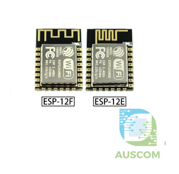
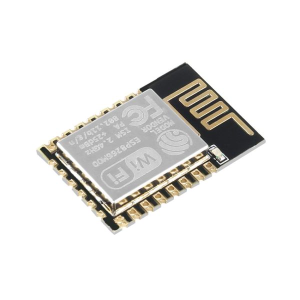
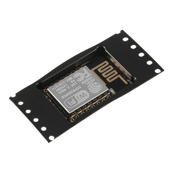
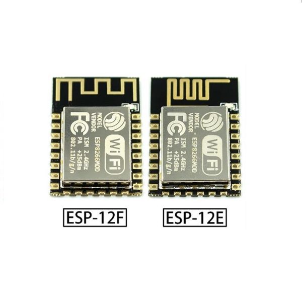
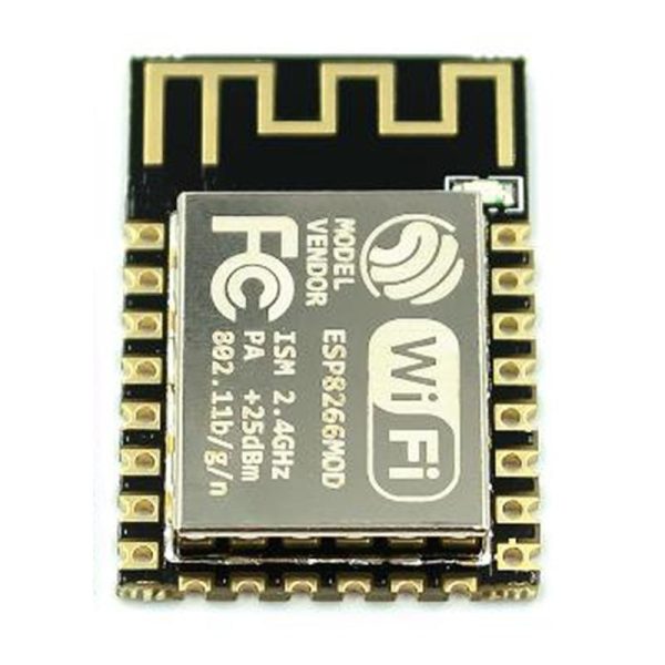
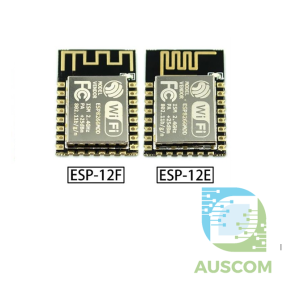

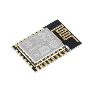

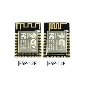
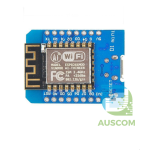
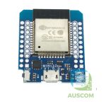
ESP-12E ESP-12F ESP8266 Remote Serial Port WIFI Module Arduino
Price range: $6.99 through $8.90 Inc. GST
You save
- Description
- Code Examples
- Additional information
- Reviews (0)
Description
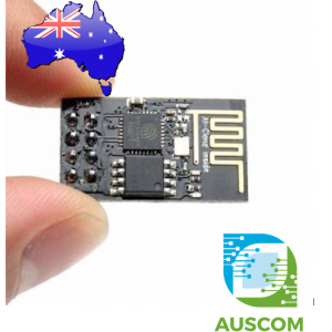
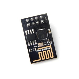
Revolutionize your Arduino projects with the ESP-12E/ESP-12F ESP8266 Remote Serial Port WiFi Module!
Type: ESP-12F/ESP-12E Certifications: FCC / CE / TELEC Wireless Standards: 802.11 b/g/n Frequency Range: 2.4GHz-2.5GHz (2400M-2483.5M) Data Interfaces: UART / HSPI / I2C / I2S / IR Remote Control GPIO / PWM Voltage Range: 3.0 ~ 3.6V (recommended: 3.3V) Current Consumption: Average: 80mA Operating Temperature: -40°C ~ 125°C Storage Temperature: Normal Temperature
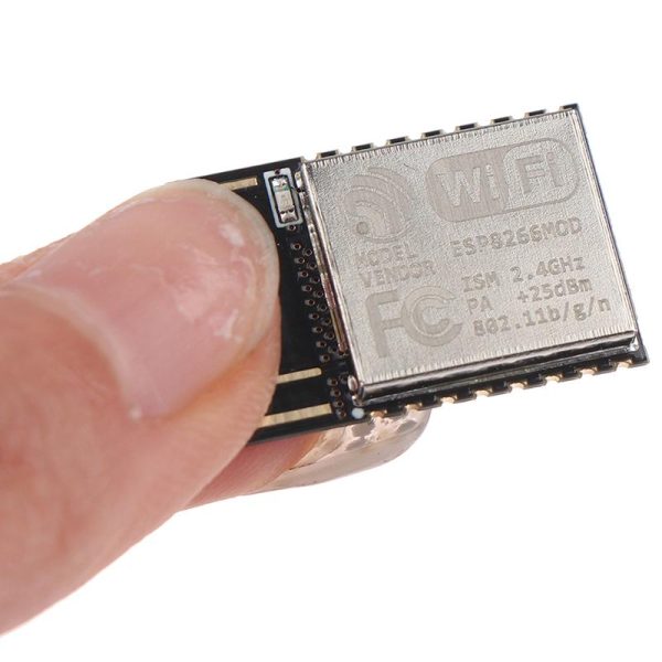
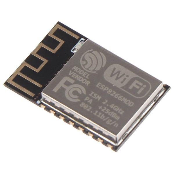
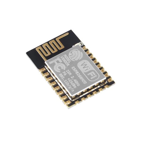
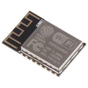
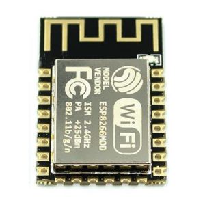
Unlock the potential of your next Arduino endeavor with this budget-friendly microcontroller module, seamlessly integrated with Wi-Fi capabilities! A part of the ESP8266 series, this module represents a pinnacle in wireless System On a Chip (SOC) technology. Perfectly tailored for minimal space requirements, it provides a comprehensive standalone Wi-Fi networking solution at an unparalleled cost efficiency. Whether hosting applications or delegating Wi-Fi networking functions, this module shines. Boasting an embedded PCB antenna and 9 GPIOs plus ADC, it’s an ideal fusion of versatility and compactness.
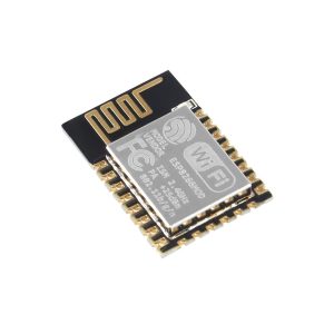
A step above its predecessor, the ESP-12F builds on the ESP-12E, flaunting 22 pins and an enhanced antenna design that bolsters communication range by 30% to 50% compared to its 16-pin counterpart. This FCC, CE, and RoHS certified marvel remains fully compatible with earlier editions of the ESP-12 series.
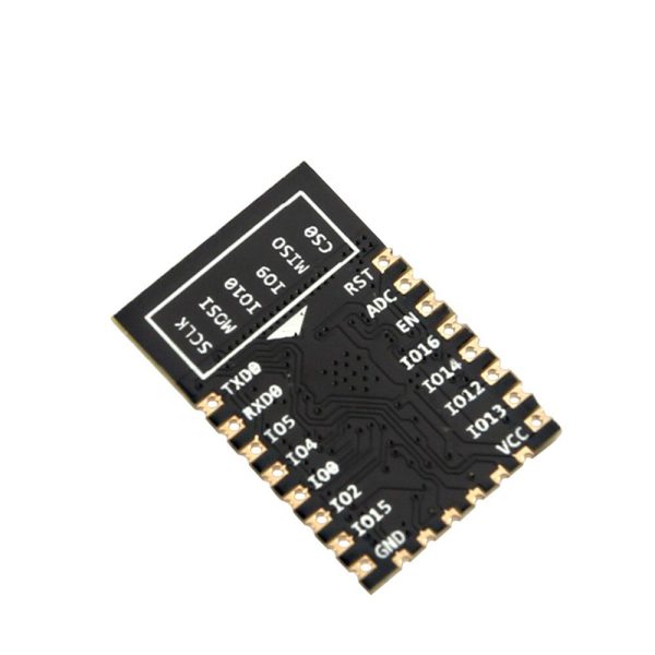
Pinpointing the Ideal Configuration:
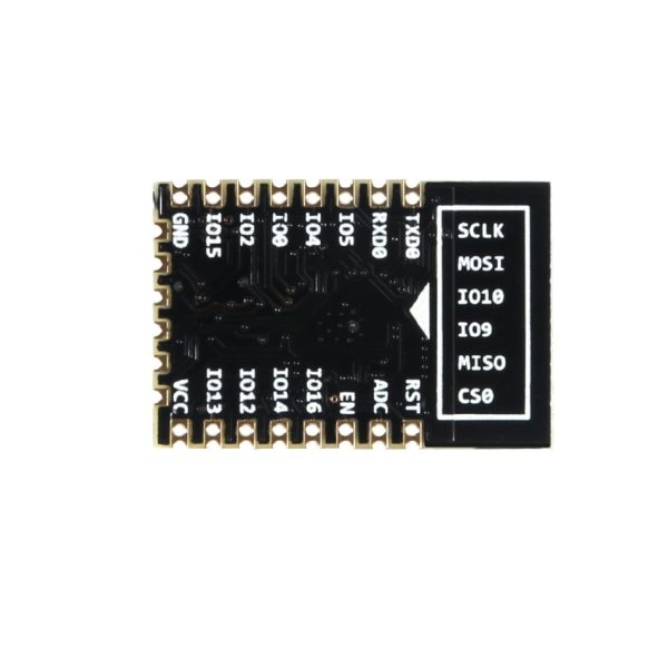
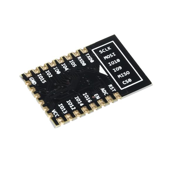
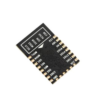
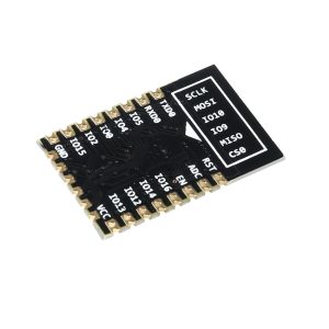
- RST: Reset the module
- ADC: A/D Conversion result, voltage range 0-1V, scale: 0-1024
- EN: Chip enable pin, active in high state
- GPIO16: Wake chipset from deep sleep mode
- GPIO14: HSPI_CLK
- GPIO12: HSPI_MISO
- GPIO13: HSPI_MOSI, UART0_CTS
- VCC: 3.3V power supply (VDD)
- CS0: Chip selection
- MISO: Slave output main input
- IO9: GPIO9
- IO10: GPIO10
- MOSI: Main output slave input
- SCLK: Clock
- GND: Ground
- GPIO15: MTDO, HSPICS, UART0_RTS
- GPIO2: UART1_TXD
- GPIO0
- GPIO4
- GPIO5
- RXD: UART0_RXD, GPIO3
- TXD: UART0_TXD, GPIO1
Enriching Features:
- 802.11 b/g/n support
- Integrated 32-bit low-power MCU
- Built-in 10-bit ADC
- Comprehensive TCP/IP protocol stack
- Onboard TR switch, balun, LNA, power amplifier, and matching network
- Inclusive PLL, regulators, and power management units
- Antenna diversity support
- Wi-Fi 2.4GHz, WPA/WPA2 compatibility
- Modes: STA/AP/STA+AP
- Seamless Smart Link Function for Android and iOS
- Versatility: SDIO 2.0, (H) SPI, UART, I2C, I2S, IRDA, PWM, GPIO
- Advanced configurations: STBC, 1×1 MIMO, 2×1 MIMO, A-MPDU & A-MSDU aggregation, 0.4s guard interval
- Ultra-low power consumption: <10uA in deep sleep, <5uA power down leakage
- Rapid wake-up and packet transmission in <2ms
- Standby power use <1.0mW (DTIM3)
- +20dBm output power in 802.11b mode
- Operating temperature range: -40°C ~ 125°C
- FCC, CE, and RoHS certified
Vital Specifications:
Wi-Fi Essentials
- Certificates: FCC/CE/RoHS
- Wi-Fi Protocols: 802.11 b/g/n
- Frequency Spectrum: 2.4GHz-2.5GHz (2400M-2483.5M)
Hardware Highlights
- Peripheral Bus: UART/HSPI/I2C/I2S/IR Remote Control, GPIO/PWM
- Power Range: 3.0~3.6V
- Operating Current: Averaging 80mA
- Temperature Range: Operating: -40°C~125°C, Ambient: Normal Temperature
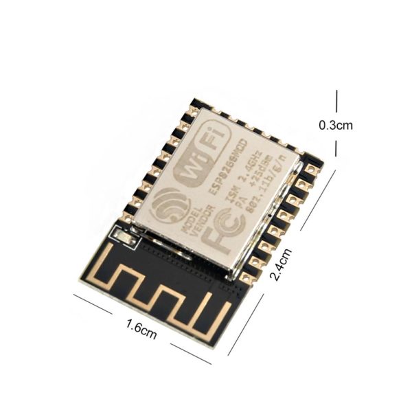
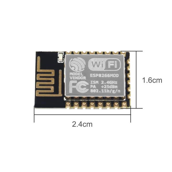
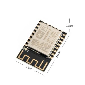
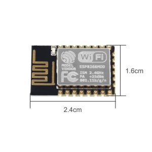
- Dimensions: 16mm x 24mm x 3mm
Software Excellence
- Wi-Fi Modes: Station/SoftAP/SoftAP+Station
- Security: WPA/WPA2, Encryption: WEP/TKIP/AES
- Firmware Upgrades: UART Download / OTA (via network) / Host-assisted firmware downloads
- Software Development: Cloud Server Development Support / SDK for customized firmware
- Network Protocols: IPv4, TCP/UDP/HTTP/FTP
- User Configuration: AT Instruction Set, Cloud Server Integration, Android/iOS App Compatibility
Package Contents:
1x ESP8266 ESP-12E/F WiFi Module
Unleash the ESP-12E/ESP-12F ESP8266 WiFi Module and transform your Arduino creations into connected wonders!
📌 Code Examples & Usage – ESP-12E / ESP-12F ESP8266 WiFi Module
📋 Overview
The ESP-12E / ESP-12F modules are based on the ESP8266 WiFi SoC and provide full TCP/IP networking with a powerful 32-bit microcontroller.
They are commonly used for:
-
WiFi-enabled IoT projects
-
Remote serial communication
-
Smart switches & relays
-
Sensors & data logging
-
Home automation
-
Custom embedded products
⚠ These are bare modules and require correct power, boot configuration, and programming connections.
⚠ Important Electrical Notes (READ FIRST)
-
Operating voltage: 3.3 V ONLY
-
Not 5 V tolerant
-
Can draw 300–500 mA peak during WiFi transmission
-
Requires a stable 3.3 V regulator (AMS1117 or better)
❌ Do NOT power directly from Arduino 3.3 V pin
✔ Use a dedicated 3.3 V supply
🔌 Minimum Required Connections
Power
| Pin | Connect To |
|---|---|
| VCC | 3.3 V |
| GND | GND |
Boot Configuration (MANDATORY)
| Pin | State | Notes |
|---|---|---|
| EN / CH_PD | HIGH | Enable chip |
| GPIO0 | HIGH (normal run) / LOW (flash) | Boot mode |
| GPIO2 | HIGH | Required at boot |
| GPIO15 | LOW | Required at boot |
Incorrect boot wiring = module will not start.
🔌 Programming (UART)
| ESP-12 Pin | USB-TTL Adapter |
|---|---|
| TXD | RX |
| RXD | TX |
| GND | GND |
⚠ Use 3.3 V TTL adapter only (CP2102 / CH340 with 3.3 V logic).
🔄 Boot Modes Explained (Very Important)
🔹 Normal Operation
🔹 Flash / Upload Mode
➡ After uploading code, set GPIO0 back to HIGH and reset.
📦 Arduino IDE Setup
-
Open Arduino IDE
-
Go to File → Preferences
-
Add this URL to Additional Boards Manager URLs:
-
Open Boards Manager
-
Install ESP8266 by ESP8266 Community
-
Select board: Generic ESP8266 Module
-
Settings:
-
Flash Mode: DIO
-
Flash Size: 4M (ESP-12E/F)
-
Baud Rate: 115200
-
🧪 1️⃣ Arduino Example – Blink (Basic Test)
✔ If this works, your wiring and power are correct.
🌐 2️⃣ WiFi Connection Example
🔁 3️⃣ Remote Serial (WiFi → UART Bridge)
Simple TCP serial bridge example:
✔ Great for remote debugging and serial control over WiFi.
🧠 Common Problems & Fixes
| Issue | Cause | Fix |
|---|---|---|
| No boot | Wrong GPIO states | Check GPIO0/2/15 |
| Random resets | Weak 3.3 V supply | Use better regulator |
| Upload fails | GPIO0 not LOW | Set flash mode |
| WiFi drops | Noise / power dip | Add bulk capacitor |
Recommended:
Add 470–1000 µF capacitor close to VCC/GND.
Additional information
| Weight | 30 g |
|---|---|
| Dimensions | 260 × 160 × 20 mm |
| ESP Model | 12E, 12F |
Only logged in customers who have purchased this product may leave a review.
You may also like…
-
 Programming & Debugging Tools
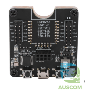
ESP8266 Downloader Tool Wifi Module Development Socket ESP-12F ESP-07S ESP-12E ESP-01S ESP12S
$18.93 - $22.95 Inc. GST
You save
















Reviews
There are no reviews yet.