
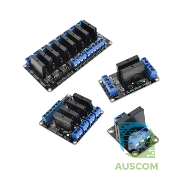
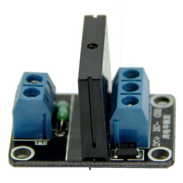
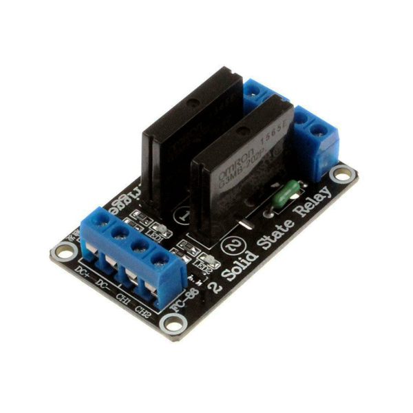
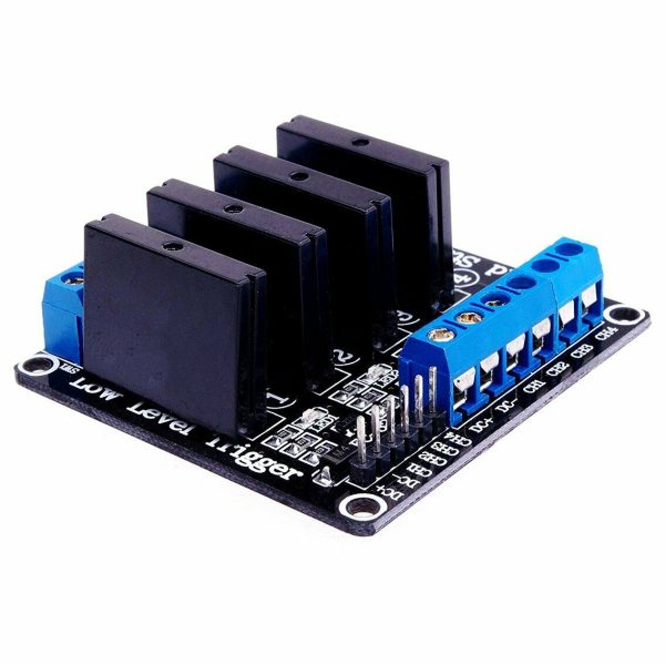
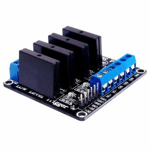
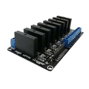
1/2/4/8 Channel Solid State Relay Module SSR Low Level 5V 2A Arduino
Price range: $7.95 through $26.95 Inc. GST
You save
- Description
- Code Examples
- Additional information
- Reviews (0)
Description
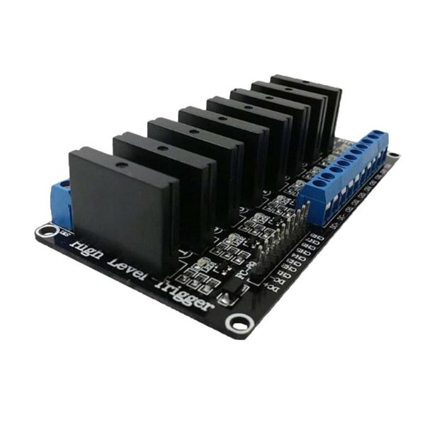
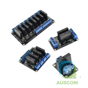
Introducing our versatile Solid State Relay (SSR) Modules, available in 1, 2, 4, and 8-channel configurations, designed to provide seamless control and reliability for your projects. Engineered for efficiency and compatibility with Arduino and other microcontrollers, these SSR Modules offer a superior solution for a range of applications.
Key Features:
- High-Quality Performance: Each 5V solid state relay boasts a remarkable 240V 2A capacity, complemented by an integrated resistive fuse for enhanced safety and durability.
- Flexible Sizing Options: Choose the perfect fit for your setup:
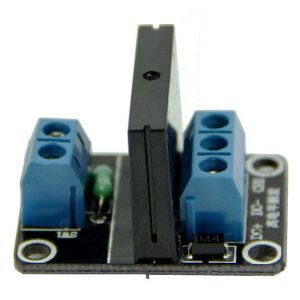
- 1-channel: 25 * 34 * 25 (L * W * H)
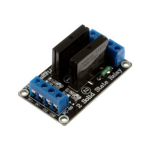
- 2-channel: 55 * 33 * 25 (L * W * H)
- 4-channel: 57 * 55 * 25 (L * W * H)
- 8-channel: 106 * 56 * 25 (L * W * H)
- Effortless Integration: Powered by a 5V DC input (160mA), these modules facilitate easy compatibility with various systems.
- Precise Control Signal: Tailor your control with high and low-level trigger options:
- High-Level: Relay ON with 0-2.5V signal, OFF with 3.3-5V signal
- Low-Level: Relay OFF with 0-2.5V signal, ON with 3.3-5V signal
- User-Friendly Design: Experience seamless connectivity with 2.54CM pins and the convenient blue KF301 terminal control lines.
Input Section:
- DC +: Connect to positive power supply (matching relay voltage)
- DC -: Connect to negative power supply
- CH1/CH2/CH3/CH4: Signal trigger terminals for each relay module (low-level trigger active)
High and Low Trigger Explanation:
- High-Level Trigger: Voltage between signal trigger side (IN) and negative power supply is positive, resulting in relay activation upon reaching trigger voltage.
- Low-Level Trigger: Voltage between signal trigger terminal and negative terminal of power supply is ≤0V, or lower than positive terminal voltage. Relay activates when trigger voltage is sufficiently low.
Electrical Parameters:
| Channels | Voltage | Quiescent Current | Operating Current | Trigger Voltage | Trigger Current |
|---|---|---|---|---|---|
| 1 | 5V | 0mA | 12.5mA | 0-2.5V | 2mA |
| 2 | 5V | 0mA | 22.5mA | 0-2.5V | 2mA |
| 4 | 5V | 0mA | 48mA | 0-2.5V | 2mA |
| 8 | 5V | 0mA | 102mA | 0-2.5V | 2mA |
Product Manual:
- Module Power Supply: Ensure a matching DC voltage for the power supply and relay voltage.
- Wiring Method: Activate the relay by providing the appropriate signal trigger level. The device will then energize and perform its intended function.
Precautions:
- Module Power Supply: Exclusive use of 5V DC power supply is mandatory.
- Module Control Terminal Voltage: These modules are optimized for AC current control and cannot regulate DC currents.
Elevate your project with our feature-rich Solid State Relay Modules, offering optimal control and precision. Choose the configuration that aligns with your needs and experience enhanced performance like never before.
📌 Code Examples & Usage – Solid State Relay (SSR) Module (1 / 2 / 4 / 8 Channel)
📋 Overview
This solid state relay (SSR) module allows a low-voltage control signal from a microcontroller to safely switch AC or DC loads using solid-state electronics instead of mechanical contacts.
SSR modules are ideal for:
-
Silent switching
-
High switching frequency
-
Long service life (no mechanical wear)
-
Resistive AC loads
-
Automation & control systems
Available in 1, 2, 4, and 8 channel versions.
⚠ IMPORTANT – Read Before Use
🚨 This is a LOW-POWER SSR module
-
Control voltage: 5V (logic input)
-
Trigger type: LOW-level trigger
-
Output current: up to 2A per channel
-
Output type: solid-state (triac or MOSFET, module dependent)
⚠ Not suitable for high-current loads
⚠ Not suitable for inductive loads without proper precautions
⚙ Key Characteristics
-
Silent operation (no clicking)
-
Long lifespan
-
Fast switching
-
Optically isolated inputs (module dependent)
-
Logic compatible with Arduino & ESP32
🔌 Control Side Wiring (Low Voltage)
Control Pins
| Pin | Function |
|---|---|
| IN1…INx | Relay control inputs |
| VCC | 5V logic supply |
| GND | Ground |
📌 LOW-level trigger
-
LOW (0V) → Relay ON
-
HIGH (5V / 3.3V) → Relay OFF
ESP32 (3.3V logic) works reliably.
🔌 Load Side Wiring (Output)
Each channel has two output terminals:
| Terminal | Function |
|---|---|
| LOAD+ / AC1 | Load input |
| LOAD- / AC2 | Load output |
📌 There is no polarity for AC loads
📌 For DC SSRs, observe polarity if marked
🧪 1️⃣ Arduino Example – Single Channel Control
✔ Silent switching
✔ Ideal for lamps, heaters, and resistive loads
🧪 2️⃣ Arduino Example – Multiple Channels
Works with 2, 4, or 8 channel boards.
🧪 3️⃣ ESP32 Example
✔ 3.3V logic compatible
✔ No level shifter required
⚡ AC Load Notes (VERY IMPORTANT)
Most SSR modules use triac outputs, which means:
✔ Best for AC resistive loads
-
Heaters
-
Incandescent lamps
-
Some power supplies
⚠ Not recommended for:
-
Induction motors
-
Transformers
-
Large solenoids
-
Loads with high inrush current
👉 For inductive loads, use:
-
Mechanical relays
-
Zero-cross SSRs rated for inductive loads
-
Snubber circuits
🔥 Heat & Derating (Critical)
SSR modules generate heat when conducting.
✔ Recommended:
-
Keep load current below maximum rating
-
Provide airflow
-
Use a heatsink for continuous loads
-
Do not enclose tightly without ventilation
Rule of thumb:
Continuous current ≤ 50–60% of rated value
🧠 SSR vs Mechanical Relay (Quick Comparison)
| Feature | SSR | Mechanical Relay |
|---|---|---|
| Noise | Silent | Clicks |
| Lifespan | Very long | Limited |
| Speed | Fast | Slow |
| Power loss | Higher | Low |
| Inductive loads | ❌ | ✅ |
| Cost | Higher | Lower |
🧠 Tips & Best Practices
✔ Use SSRs for frequent switching
✔ Use mechanical relays for motors
✔ Always confirm load type (AC/DC)
✔ Keep wiring short and secure
✔ Use fuses on AC loads
Additional information
| Weight | 100 g |
|---|---|
| Dimensions | 260 × 160 × 50 mm |
| Channels | 1, 2, 4, 8 |
Only logged in customers who have purchased this product may leave a review.


Reviews
There are no reviews yet.