
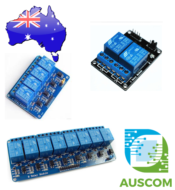
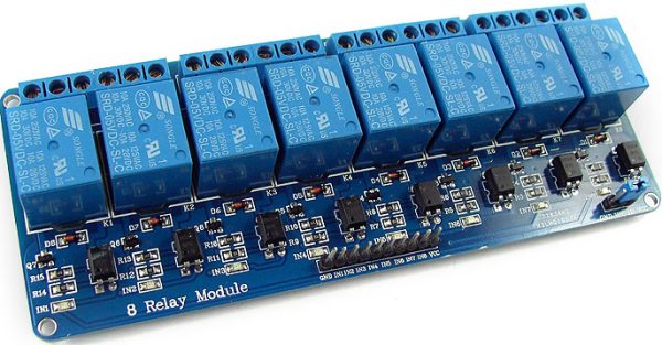
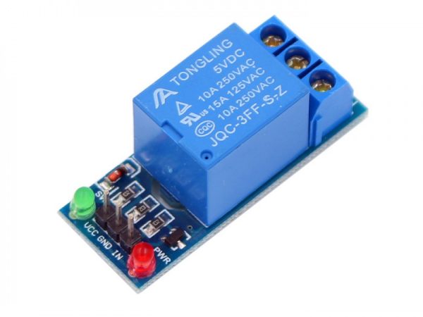
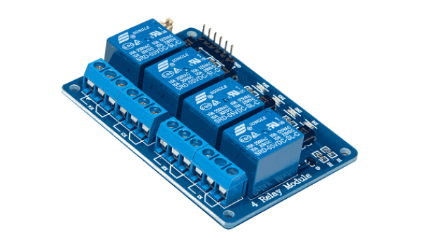
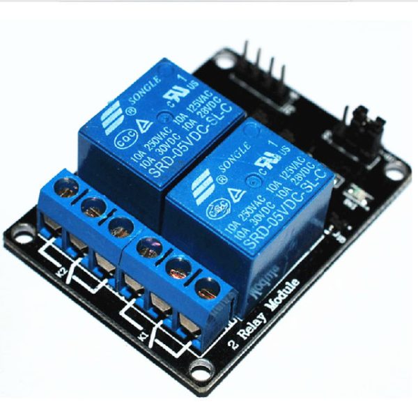
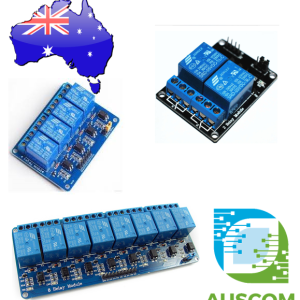
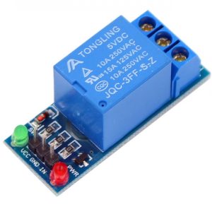
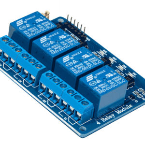
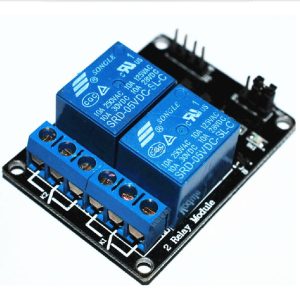
1 / 2 / 4 / 6 / 8 Channel 5V 10A Relay Board Module for Arduino Raspberry Pi
Price range: $7.50 through $17.90 Inc. GST
You save
- Description
- Code Examples
- Additional information
- Reviews (0)
Description
Enhance Your Control with 5V 10A Relay Board Modules for Arduino and Raspberry Pi
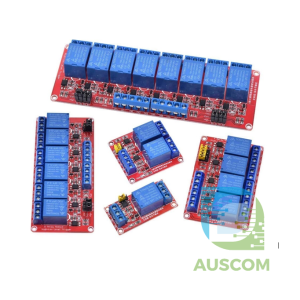
Experience the utmost control and efficiency with our versatile 1 / 2 / 4 / 6 / 8 Channel 5V 10A Relay Board Module, perfectly tailored for seamless integration with Arduino and Raspberry Pi platforms.
Key Features:
- Premium 5V Relay: Immerse yourself in reliable performance with our high-quality 5V relay, ensuring secure and consistent connectivity.
- Intuitive Status Indicators: Stay informed at a glance with built-in relay status indicator LEDs, providing clear insights into your system’s operations.
- Simplified Setup: Enjoy effortless integration with its straightforward 3-line structure, making usage a breeze for users of all levels.
- Powerful Appliance Control: Effortlessly manage a wide array of appliances and high-current equipment, granting you ultimate command over your devices.
- Versatile Applications: Perfectly suited for MCU control, industrial sectors, PLC management, and smart home automation, enabling boundless possibilities.
Specifications:
- Channels: 1/2/4/6/8, directly compatible with microcontrollers
- LED Indicators: Offers visual cues for immediate status recognition
- Switching Capacity: Up to 10A, ensuring robust performance
- Maximum Voltage: 250VAC / 30VDC for versatile compatibility
Designed for Your Needs:
- Low Level Trigger: While this version features a low level trigger, our store also offers relays with high-level trigger options, granting you the flexibility to choose based on your requirements.
Package Includes:
- 1 x Relay Board Module
Please note that the relay brand may vary depending on availability, but rest assured, all relays adhere to the same exceptional quality and specifications that you expect from us.
Elevate your control capabilities today with our feature-rich 5V 10A Relay Board Modules. Unleash the potential of your projects with enhanced precision and reliability.
📌 Code Examples & Usage – 5V Relay Board Module (1 / 2 / 4 / 6 / 8 Channel, LOW-Level Trigger)
📋 Overview
This 5V relay board module provides isolated switching of AC or DC loads using low-voltage control signals from microcontrollers, PLC outputs, and single-board computers.
This product is available in 1-channel, 2-channel, 4-channel, 6-channel, and 8-channel versions and uses a LOW-level trigger input, which is common in industrial and automation applications.
Typical applications include:
-
Home & building automation
-
PLC output expansion
-
Switching lights, pumps, fans, solenoids
-
Arduino, ESP32, ESP8266, Raspberry Pi projects
-
Test rigs and control panels
Each relay is typically rated up to 10A @ 250VAC or 30VDC (check relay markings on your board).
⚙ Key Features
-
Relay coil voltage: 5V
-
Contact rating: Up to 10A
-
Channel options: 1 / 2 / 4 / 6 / 8
-
LOW-level trigger inputs
-
Compatible with 3.3V and 5V logic
-
Optocoupler isolation (board dependent)
-
Screw terminals for load wiring
⚠ IMPORTANT – Trigger Logic (READ THIS)
🚨 This is a LOW-LEVEL TRIGGER relay board
| Input State | Relay State |
|---|---|
| LOW (0V) | Relay ON |
| HIGH (5V) | Relay OFF |
✔ This behaviour is normal
✔ Not a fault or wiring issue
✔ Suitable for PLC and MCU outputs
📌 Always initialise relay pins HIGH on startup to prevent accidental activation.
🔌 Relay Contact Terminals
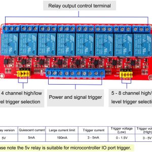
Each relay provides three terminals:
| Terminal | Function |
|---|---|
| COM | Common |
| NO | Normally Open (OFF → ON when activated) |
| NC | Normally Closed (ON → OFF when activated) |
📌 Most applications use COM + NO.
🔌 Control Pinout (Typical)
| Pin | Function |
|---|---|
| VCC | 5V |
| GND | Ground |
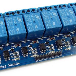
| IN1…INx | Relay control inputs |
📌 Some boards include JD-VCC to separate relay coil power from logic power.
🔌 Wiring – Arduino Example (6-Channel Board)
| Relay Board | Arduino |
|---|---|
| VCC | 5V |
| GND | GND |
| IN1 | D2 |
| IN2 | D3 |
| IN3 | D4 |
| IN4 | D5 |
| IN5 | D6 |
| IN6 | D7 |
🧪 1️⃣ Basic Example – Single Relay (LOW-Trigger)
🧪 2️⃣ Multi-Channel Example (1–8 Channels)
⚡ Inductive Load Protection (Strongly Recommended)
When switching motors, pumps, solenoids, contactors:
DC Loads
-
Fit a flyback diode across the load
-
Example: 1N4007, FR107, SS14
AC Loads
-
Use an RC snubber (e.g. 100Ω + 100nF)
-
Or a MOV across the load
📌 This reduces:
-
Relay contact wear
-
Electrical noise
-
MCU resets and interference
🔋 Power Consumption Notes
-
Each relay coil typically draws 70–90 mA
-
6-channel board: ~450–550 mA
-
8-channel board: >600 mA
⚠ Do not power multi-channel relay boards from MCU onboard regulators.
🧠 Common Issues & Fixes
| Issue | Cause | Fix |
|---|---|---|
| Relay turns ON at boot | Floating pin | Set pin HIGH in setup() |
| ESP resets | Power sag | Use external 5V supply |
| Clicking but no load | Wrong terminals | Use COM + NO |
| Noise issues | Inductive loads | Add suppression |
| Overheating | Load too large | Use contactor |
Additional information
| Weight | 130 g |
|---|---|
| Dimensions | 260 × 160 × 20 mm |
| # of Channels | 1, 2, 4, 6, 8 |
Only logged in customers who have purchased this product may leave a review.










Reviews
There are no reviews yet.