


IR Transmitter & Receiver 38 kHz Secure Non-Radio Sensor Kit for Arduino ESP32

Price range: $10.60 through $12.50 Inc. GST
You save
- Description
- Code Examples
- Additional information
- Reviews (0)
Description
🔦 IR Infrared Transmitter & Receiver Module – Secure 38 kHz Digital Sensor Kit for Arduino
Overview
The IR Infrared Transmitter and Receiver Sensor Module Kit provides secure, interference-free communication for your Arduino, ESP32, or Raspberry Pi projects.
Unlike wireless radio modules (RF, Wi-Fi, or Bluetooth), infrared communication is immune to radio-frequency interference and non-radio detectable, making it perfect for noise-sensitive or stealth control applications.
This set includes the HX-53 IR Transmitter and the HX-M121 IR Receiver modules. They operate at 38 kHz — ideal for remote-control systems, obstacle detection, or infrared data links — and can be purchased individually or as a complete kit.
⚙️ Key Features
-
🔹 Secure IR communication — non-radio, interference-resistant, and undetectable by RF scanners
-
🔹 38 kHz digital signal for reliable remote-control operation
-
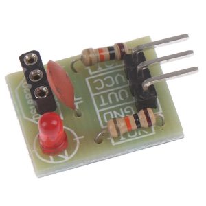
🔹 HX-53 transmitter and HX-M121 receiver with 3-pin Arduino-compatible headers
-
🔹 940 nm infrared LED with ~1.3 m range (5 V @ 38 kHz)
-
🔹 Receiver includes data indicator LED and dual mounting holes
-
🔹 Fully compatible with Arduino, ESP8266, ESP32, Raspberry Pi, STM32, and most 5 V controllers
-
🔹 Ideal for environments where radio interference or RF detection is a concern
📊 Specifications
| Parameter | Transmitter (HX-53) | Receiver (HX-M121) |
|---|---|---|
| Operating Voltage | 5 V DC | 5 V DC |
| Signal Type | Digital | Digital |
| Wavelength | 940 nm | 850–840 nm |
| Emission Angle | ≈ 20° | — |
| Effective Range | ≈ 1.3 m (5 V @ 38 kHz) | — |
| Operating Temp. | −25 °C to +85 °C | −25 °C to +85 °C |
| Storage Temp. | −30 °C to +100 °C | −30 °C to +100 °C |
| Mounting Holes | 2 × 3.1 mm | 2 × 3.1 mm |
| Interface Pins | DAT, VCC, GND | DAT, VCC, GND |
| Output Type | Digital | Digital |
🧩 Applications
✅ Arduino remote-control and communication projects
✅ Secure, non-radio data transmission
✅ Obstacle-avoidance sensors for robotics
✅ Infrared data links and object detection
✅ RF-sensitive or stealth environments
✅ DIY electronics, automation, and educational kits
📦 Package Options
-
Transmitter Module (HX-53)
-
Receiver Module (HX-M121)
-
Transmitter + Receiver Kit (both modules)
📌 Code Examples – HX-53 IR Transmitter & HX-M121 IR Receiver (38 kHz)
📋 Module Overview
This kit includes:
-
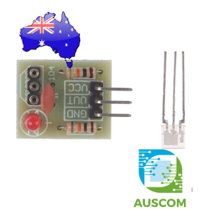
HX-53 IR Transmitter module – IR LED driver board with:
-
VCC, GND, DATA (signal) pins Arduino Stack Exchange+1
-
-
HX-M121 IR Receiver module – 38 kHz IR receiver with:
-
VCC, GND, OUT (digital output) pins Amazon Media+1
-
They’re designed to work together as a simple line-of-sight, non-radio link or to receive standard IR remote signals (38 kHz carrier).
🔌 Pinouts
🔹 HX-53 IR Transmitter (3-pin)
-
VCC – 5 V supply
-
GND – Ground
-
DATA – Digital input (drive with 38 kHz signal or on/off pulses)
The module includes current-limiting resistor + indicator LED, so you can drive it directly from a microcontroller pin at 5 V. Arduino Stack Exchange+1
🔹 HX-M121 IR Receiver (3-pin)
-
VCC – 5 V
-
GND – Ground
-
OUT – Digital output (goes low when 38 kHz IR is detected)
The receiver demodulates the 38 kHz signal and outputs a clean digital signal suitable for direct use by microcontrollers. Amazon Media
🔧 Basic Wiring – Arduino UNO
Transmitter (HX-53)
-
VCC → 5 V
-
GND → GND
-
DATA → D3 (we’ll use this with
tone()at 38 kHz)
Receiver (HX-M121)
-
VCC → 5 V
-
GND → GND
-
OUT → D11 (any digital pin works)
📝 You can run both modules from the same Arduino for testing, or use two boards (one as transmitter, one as receiver).
🧪 Example 1 – Simple Beam Test (no extra libraries)
This is the easiest way to prove the kit works:
-
Arduino generates a 38 kHz carrier on the HX-53
-
HX-M121 output is read as a digital signal
How to test:
-
Power the Arduino with both modules connected
-
Open Serial Monitor (9600 baud)
-
Point the HX-53 at the HX-M121
-
You should see “IR signal detected” when they’re aligned and close
Move the transmitter away or block it → messages stop.
📡 Example 2 – Using HX-M121 as a Remote Receiver (IRremote library)
If you want to use the HX-M121 with a normal TV-style remote, you can use the IRremote library.
🔧 Install: Arduino IDE → Tools → Manage Libraries… → search “IRremote”
Receiver Wiring
-
HX-M121 VCC → 5 V
-
HX-M121 GND → GND
-
HX-M121 OUT → D11
Code
Press buttons on a standard IR remote aimed at the HX-M121 → you’ll see codes in the Serial Monitor.
⚡ Example 3 – ESP32 Pair Test
ESP32 uses 3.3 V logic. Many HX-53 boards will light at 3.3 V, but range is reduced. For safety:
-
Option A: Run HX-53 VCC from 5 V, DATA from GPIO via a transistor/driver
-
Option B: Run whole kit at 3.3 V if your modules still work at that voltage (shorter range but easy)
Here’s a basic receiver example on ESP32 assuming HX-M121 is powered by 3.3 V and OUT goes to GPIO17:
📡 Example 4 – Simple IR Communication Between Two Arduinos
This demo sends a byte value (0–255) from one Arduino to another using the HX-53 + HX-M121 pair.
🔹 Transmitter: Turns 38 kHz ON briefly for each “1” bit
🔹 Receiver: Detects IR presence using digitalRead()
This is not a full protocol (like NEC), just a simple educational demo that customers can build on.
🔧 Transmitter Wiring (Arduino #1) – HX-53 IR Transmitter
| HX-53 Pin | Arduino |
|---|---|
| VCC | 5V |
| GND | GND |
| DATA | D3 |
We use tone() on pin 3 to generate the 38 kHz carrier.
🔧 Receiver Wiring (Arduino #2) – HX-M121 IR Receiver
| HX-M121 Pin | Arduino |
|---|---|
| VCC | 5V |
| GND | GND |
| OUT | D11 |
The receiver outputs LOW when IR is detected.
🛫 Transmitter Code (Send a Byte Repeatedly)
🛬 Receiver Code (Decode the IR Bit Stream)
🧠 How It Works
Transmitter
-
Uses
tone()to generate a 38 kHz signal when sending a 1 -
Turns carrier off to send a 0
-
Sends a start bit, then 8 data bits, then stop bit
Receiver
-
HX-M121 outputs LOW when 38 kHz is detected
-
Reads each bit once per BIT_DURATION window
-
Reconstructs the byte and prints it
🧪 What You Should See
On the Transmitter Serial Monitor:
On the Receiver Serial Monitor:
🚀 Next Possible Enhancements
-
Add checksums for reliable data transfer
-
Reduce BIT_DURATION for higher speed
-
Use IRremote library for full NEC-format communication
-
Add LED indicators showing transmit/receive activity
- Combine with sensors to send wireless analog/digital readings
🧠 Tips & Notes
-
Make sure the modules face each other with no big obstructions
-
Typical effective range is a few metres, depending on supply voltage and alignment Shopee Malaysia
-
For two-Arduino comms, you can encode bits by turning the 38 kHz on/off (e.g. using
tone()andnoTone()or IR libraries) -
For TV/AC remotes, use the IRremote library and the HX-M121 alone
Additional information
| Weight | N/A |
|---|---|
| Dimensions | N/A |
| Module | Transmitter, Receiver, Kit |
Only logged in customers who have purchased this product may leave a review.














Reviews
There are no reviews yet.