
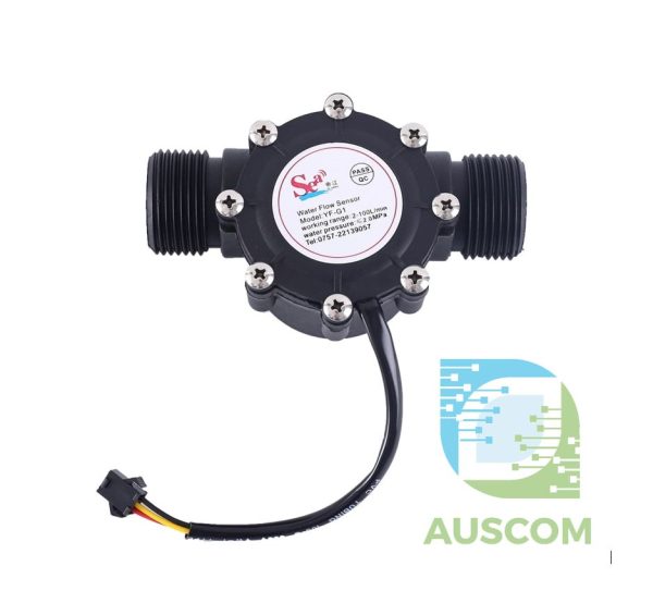
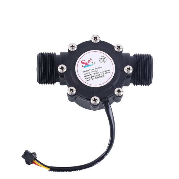
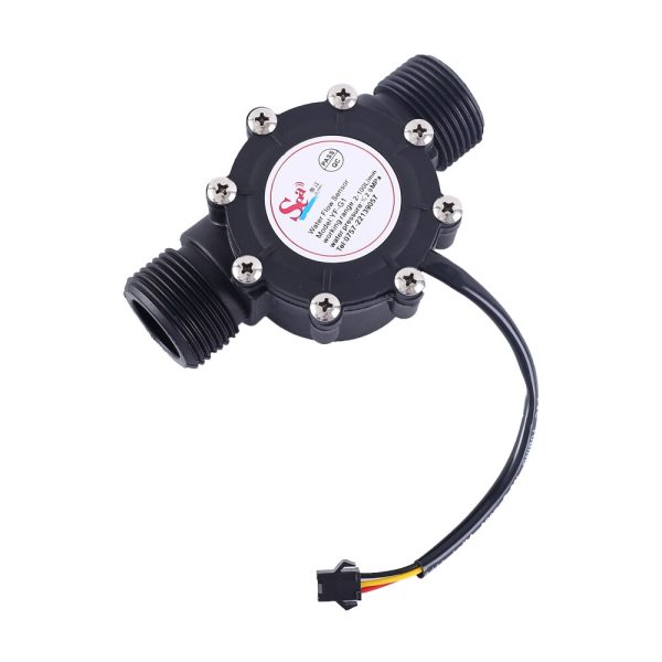

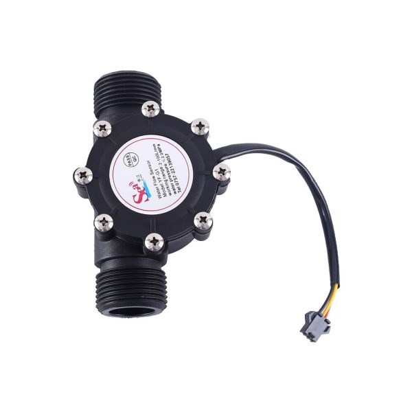
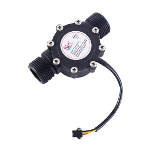
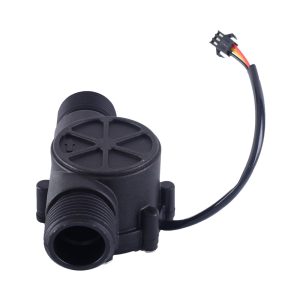
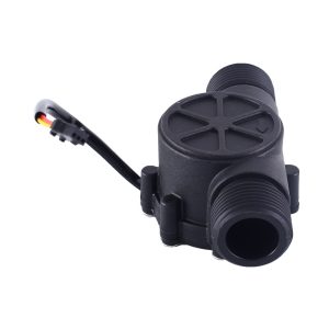
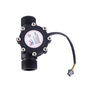
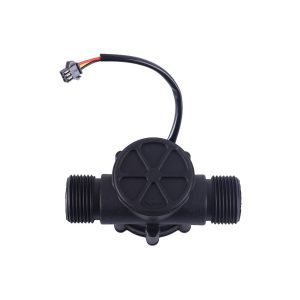
SEA YF-G1 Water Flow Sensor G1″ 1–100L/min Turbine Flowmeter 3.5–24V

$67.00 Inc. GST
You save
- Description
- Code Examples
- Additional information
- Reviews (0)
Description
🌊 SEA YF-G1 Water Flow Sensor G1″ Turbine Flowmeter 2–100 L/min | AuscomTech
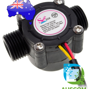
The SEA YF-G1 Water Flow Sensor is a turbine-based Hall-effect flowmeter designed for accurate and repeatable water flow measurement in monitoring, control, and automation systems.
It outputs an NPN pulse signal proportional to flow rate, making it easy to interface with microcontrollers, PLCs, data loggers, and industrial controllers for real-time water usage tracking and automated control.
With a standard G1-inch (DN25) male threaded interface, wide operating voltage range, and robust operating temperature capability, the YF-G1 is well suited to residential, commercial, and industrial water measurement applications.
⭐ Key Features
🌪️ Turbine-Based Hall Flow Measurement
Internal turbine and Hall sensor generate a stable pulse signal proportional to water flow.
📏 Wide Flow Measurement Range
Measures water flow rates from 2 to 100 litres per minute, covering both moderate and high-flow systems.
🔩 Standard G1″ (DN25) Thread Interface
Male G1-inch thread allows easy installation into common plumbing and pipework.
⚡ Wide Operating Voltage Range
Operates from DC 3.5–24V, compatible with 3.3V, 5V, and industrial control systems.
🧭 Flexible Mounting Orientation
Can be installed vertically or horizontally without affecting operation.
🌡️ Wide Operating Temperature Range
Rated for environments from -40°C to +80°C.
🧱 Durable Plastic Housing
Lightweight black plastic body suitable for clean water applications.
📊 Technical Specifications
Model: SEA YF-G1
Sensor Type: Turbine Hall-effect water flow sensor
Nominal Size: DN25
Thread Size: G1″ male
Flow Range: 2–100 L/min (max)
Output Signal: NPN pulse output
Pulse Formula:
F = 1.08 × Q (Q = L/min) ±5%
Accuracy: ±3%
Operating Voltage: DC 3.5–24V
Operating Temperature: -40°C to +80°C
Maximum Pressure: < 1.75 MPa
Measured Medium: Clean water
Housing Colour: Black
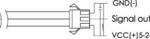
Wire Connections:
• Red: +V
• Black: GND
• Yellow: Pulse signal output (NPN)
⚠️ Important Notes
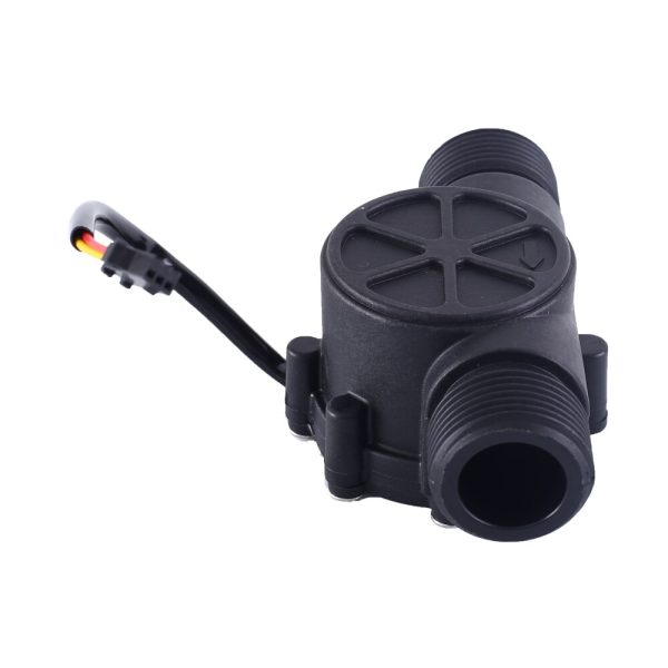
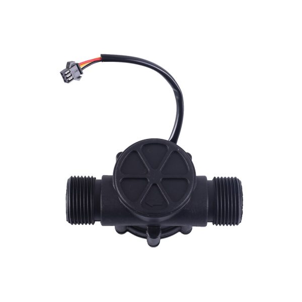
• Flow direction must match the arrow on the sensor body
• Suitable for clean water only (no debris, particles, or viscous fluids)
• Install a filter upstream if water quality is poor
• Output is a pulse signal and requires frequency counting in software
• Do not exceed rated pressure or flow limits
🧩 Compatible With
• Arduino (Uno, Mega, Nano)
• ESP32 / ESP8266
• Raspberry Pi (with suitable input conditioning)
• STM32 microcontrollers
• PLC digital input modules
• Data loggers and flow controllers
• 3.3V and 5V logic systems (with appropriate pull-ups)
⚙️ Typical Applications
• Water usage monitoring
• Irrigation and garden watering systems
• Pump flow verification
• HVAC and cooling water systems
• Industrial water management
• Building automation and control
• DIY and embedded flow measurement projects
📦 Package Includes
• 1 × SEA YF-G1 G1″ Water Flow Sensor
📌 Code Examples – High Precision SEA YF-G1 DN25 Flow Rate Meter (1–100 L/min)
📋 Overview
This is a hall-effect pulse flow meter designed for higher flow rates (1–100 L/min) with:
✔ Pulse output proportional to flow
✔ Works with DC 3–24 V
✔ Ideal for tanks, pumps, irrigation, and process monitoring
This section includes:
-
Basic wiring notes
-
Arduino example
-
ESP32 example
-
Filtering & calibration
-
Optional pump control example
⚠ Safety & Wiring Notes
| Pin | Function |
|---|---|
| Red | Power (3–24 V DC) |
| Black | GND |
| Yellow | Pulse output (open-collector) |
Because this meter is often used in systems with pumps/valves:
✔ Ensure common ground between sensor and microcontroller
✔ Use a pull-up resistor on the pulse output (e.g., 4.7 kΩ to MCU logic voltage)
✔ For flow systems with higher electrical noise, add a small capacitor (100 nF) across the sensor’s power pins
📈 Flow Rate Basics
This type of flow meter outputs a square wave on the yellow wire whose frequency is proportional to flow.
Typical formula (check your datasheet; here’s a common one):
Where K is a calibration constant. Example values for similar YF-G series are around:
But your model may differ, so you should check calibration.
🧪 1️⃣ Arduino Example – Flow Rate & Total Volume
This sketch uses an interrupt on an interrupt-capable pin (e.g., D2) to count pulses.
⚡ 2️⃣ ESP32 Example – Flow Measurement
ESP32 has multiple interrupt-capable pins.
🧠 Calibration & Accuracy
✔ Your specific sensor’s pulses per litre constant (Kfactor) may differ — check the datasheet or calibrate manually.
✔ For best accuracy, sample continuously and compute a rolling average.
✔ Electrical noise (especially from pumps) can cause false pulses — consider RC filtering or Schmitt trigger inputs.
📊 Optional – Pump Control Example
You can use the flow meter to stop a pump when a target volume is reached. Here’s a simple addition:
Make sure you use a proper relay or motor driver if controlling real pumps.
📎 Tips & Notes
✔ Use INPUT_PULLUP or external pull-up for clean signal edges.
✔ If pulses are noisy, try a 10–100 µF capacitor across Vcc/GND near the sensor.
✔ For long cable runs, consider shielded twisted pair for the pulse signal.
✔ For high-resolution logging, send data to an SD card or over Wi-Fi/BLE.
Additional information
| Weight | 200 g |
|---|---|
| Dimensions | 260 × 160 × 60 mm |
Only logged in customers who have purchased this product may leave a review.













Reviews
There are no reviews yet.