
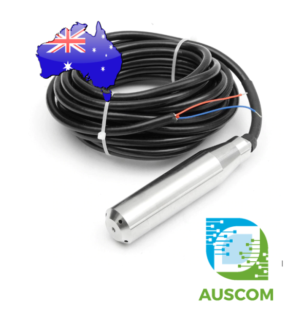
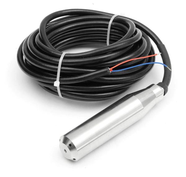
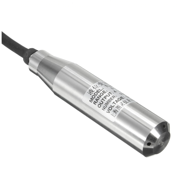
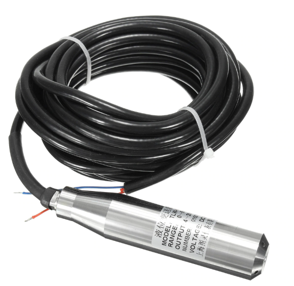
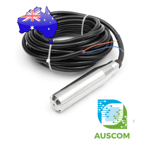
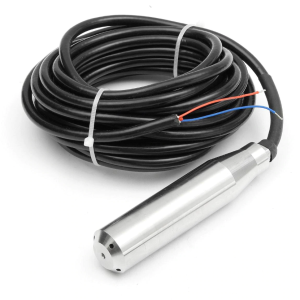
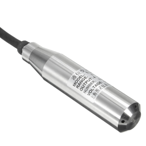
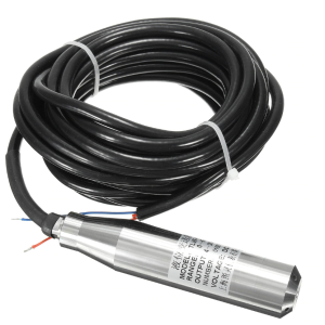
0-5m Submersible Water Level Sensor 4-20mA 12-32VDC 5m Cable IP68 Transmitter


$145.00 Inc. GST
You save (%)
- Description
- Code Examples
- Additional information
- Reviews (0)
Description
🌊 0–5m Submersible Water Level Transmitter 4-20mA 12–32VDC IP68 | AuscomTech
The YB-2J-F Submersible Liquid Level Transmitter is a high-precision water level sensor designed for continuous depth measurement in tanks, wells, reservoirs, and bore systems.
Built with a 304 stainless steel housing and IP68 waterproof protection, this transmitter uses a diffused silicon pressure sensor with full digital signal conditioning to provide a stable and accurate 4–20mA analog output.
Designed specifically for water measurement, this sensor is ideal for industrial monitoring, automation systems, PLC integration, and remote level tracking applications.
⭐ Key Features
💧 0–5 Metre Measurement Range
Designed for accurate water depth measurement up to 5 metres.
📡 Industry Standard 4–20mA Output
Stable analog current signal compatible with PLCs, data loggers, SCADA, and control systems.
⚡ Wide Supply Voltage
Operates from 12–32VDC (surface marking may show 24V, but supports full 12–32V range).
🛡️ IP68 Waterproof Rating
Fully submersible design with multi-layer sealing for long-term water immersion.
🔧 Diffused Silicon Sensing Element
High-precision internal sensor for improved measurement stability.
🧱 304 Stainless Steel Housing
Corrosion-resistant construction for water applications.
🔄 45° Anti-Impact Probe Design
Angled probe reduces blockage risk and improves durability.
📊 Technical Specifications
-
Model: YB-2J-F
-
Measurement Range: 0–5 metres
-
Output Signal: 4–20mA (analog current loop)
-
Supply Voltage: 12–32VDC
-
Measurement Accuracy: ±0.5% FS
-
Long-Term Stability: ±0.2% FS / year
-
Temperature Drift: ±0.01% FS / °C
-
Medium Temperature: -40°C to +80°C
-
Ambient Temperature: -40°C to +80°C
-
Temperature Compensation Range: -10°C to +70°C
-
Overload Protection: Built-in
-
Impact Resistance: 20g (20–5000Hz)
-
Protection Rating: IP68
-
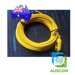
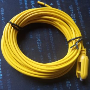
Cable Length: 5 metres (vented air guide cable)
-
Material: 304 Stainless Steel
-
Measured Medium: Clean water only
⚠️ Important Notes
• Designed for water only
• Do NOT use with corrosive liquids or chemicals
• Not recommended for liquids that attack stainless steel
• Requires appropriate 4–20mA input device for signal reading
• Must be powered within specified 12–32VDC range
🧩 Compatible With
• PLC analog input modules (4–20mA)
• Industrial controllers
• SCADA systems
• Data acquisition systems
• Arduino / ESP32 (with 4–20mA interface module)
• Water tank monitoring systems
⚙️ Typical Applications
• Bore water level monitoring
• Water tank depth measurement
• Reservoir level control
• Irrigation systems
• Pump automation systems
• Industrial water management
• Remote telemetry installations
📦 Package Includes
• 1 × YB-2J-F 0–5m Submersible Water Level Transmitter 5m vented cable
📌 Code Examples & Usage – 24VDC Submersible Water Level Transmitter (0–5m, 4–20mA)
📋 Overview
This 24VDC submersible water level transmitter is an industrial-grade hydrostatic pressure sensor designed for accurate, long-term water level measurement in tanks, wells, sumps, boreholes, and wet wells.
The sensor outputs a 2-wire 4–20mA current loop, making it ideal for:
-
PLC & SCADA systems
-
Industrial control panels
-
Pump stations & VFD monitoring
-
Data logging & telemetry
-
Arduino / ESP32 prototyping (with a shunt resistor)
Measurement range: 0–5 mH₂O (0–50 kPa)
Cable length: 6 m
Protection: IP68, stainless steel 316L housing
⚙ Key Technical Summary
-
Power supply: 24 VDC
-
Output signal: 4–20 mA (2-wire loop-powered)
-
Measurement range: 0–5 m water column
-
Accuracy: ±0.5% FS
-
Overload capacity: 2× full scale
-
Operating temperature: –20 °C to +120 °C
-
Compensation temperature: –10 °C to +80 °C
-
Protection rating: IP68
-
Material: 316L stainless steel
-
Explosion protection: Exia II CT6
⚠ IMPORTANT – Output Type (READ FIRST)
🚨 This is a 2-wire 4–20 mA sensor
-
The sensor is loop-powered
-
The same two wires provide power AND signal
-
It does NOT output voltage directly
✔ 4–20 mA is preferred in industrial systems due to:
-
High noise immunity
-
Long cable run capability
-
Fault detection (0 mA = broken loop)
🔌 Typical PLC / SCADA Wiring (Recommended Use)
Most PLCs support direct 4–20 mA analog inputs.
Standard 2-Wire Loop Wiring
📌 Always follow your PLC manufacturer’s analog input wiring guide.
🔌 Load Resistance Requirement
The sensor specifies:
Load resistance < (U − 10) / 0.02 Ω
At 24 VDC supply:
✔ Most PLC analog inputs are well within this limit.
🧪 Reading the Sensor with Arduino / ESP32 (Using a Shunt Resistor)
Microcontrollers cannot measure current directly.
A precision resistor converts the 4–20 mA signal into a voltage.
🔧 Recommended Shunt Resistor Values
| Platform | Shunt Resistor | Voltage Range |
|---|---|---|
| Arduino (5V ADC) | 250 Ω | 1.0–5.0 V |
| ESP32 (3.3V ADC) | 165 Ω | 0.66–3.3 V |
📌 Use a 0.1% or 1% metal film resistor for best accuracy.
🔌 Arduino Uno Wiring (4–20 mA)
🧪 Arduino Example – Convert 4–20 mA to Water Level (0–5m)
🧪 ESP32 Example (Recommended for IoT / Logging)
📐 4–20 mA Scaling Reference (0–5 m)
| Current | Water Level |
|---|---|
| 4.0 mA | 0.00 m |
| 8.0 mA | 1.25 m |
| 12.0 mA | 2.50 m |
| 16.0 mA | 3.75 m |
| 20.0 mA | 5.00 m |
🧠 Installation & Industrial Notes
-
Sensor measures hydrostatic pressure — assumes water density
-
Mount vertically for best accuracy
-
Secure cable with strain relief (do not suspend by cable alone)
-
Keep diaphragm clean and free of sludge
-
Ensure proper grounding for EMC performance
⚠ Safety & Handling Notes
✔ Do not disassemble the sensor
✔ Do not touch or damage the diaphragm
✔ Do not connect/disconnect wiring while powered
✔ Ensure compatibility of medium with 316L stainless steel
🧠 Common Issues & Fixes
| Issue | Likely Cause | Fix |
|---|---|---|
| Always reads 0 | No loop power | Verify 24 V supply |
| Fixed reading | Wrong wiring | Confirm 2-wire loop |
| Noisy reading | Long cable / EMI | Use shielded cable |
| PLC shows 0–10 V | Input mode wrong | Set AI to 4–20 mA |
✅ Easier Arduino Option – Use a 4–20mA → Voltage Signal Converter (Recommended)
Instead of using a shunt resistor to convert 4–20mA into a voltage, you can use a dedicated 4–20mA to voltage converter module (signal conditioner).
This approach is ideal if you want:
-
Simple wiring (no resistor selection)
-
A stable analog voltage output (e.g. 0–5V) for Arduino ADC
-
Better noise immunity and easier troubleshooting
-
Quick prototyping and data logging
🔌 Typical Wiring (Using a Converter Module)
Sensor loop (24VDC):
-
+24V → Level Transmitter (+)
-
Level Transmitter (–) → Converter IN+ (4–20mA input)
-
Converter IN– → 0V
Arduino analog output:
-
Converter VOUT (0–5V) → Arduino A0
-
Converter GND → Arduino GND
📌 Important: Ensure grounds are referenced correctly between the converter output and the Arduino.
🧪 Arduino Example – Read 0–5V From Converter and Convert to Level (0–5m)
This example assumes your converter outputs 0–5V scaled to 0–5m (common configuration):
If your converter is set to 1–5V (instead of 0–5V)
Some converters map 4–20mA → 1–5V. Use this mapping instead:
Additional information
| Weight | 700 g |
|---|---|
| Dimensions | 200 × 300 × 100 mm |
Only logged in customers who have purchased this product may leave a review.














Reviews
There are no reviews yet.