


")
- Description
- Additional information
- Reviews (0)
Description
1. Features
Multi-channel input.
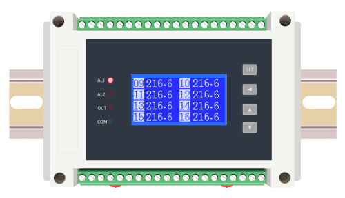
LED/Wide temperature LCD display.
With buttons, it is convenient for users to debug and set on site.
Isolated lightning protection RS485 interface, standard MODUBS-RTU communication protocol.
DIN35 rail installation.
2. Main technical indicators
| input | power supply | ||
| input signal | 8/16 channels | Supply voltage | DC10~30V |
| Accuracy | 0.2%FS 16-bit AD converter | AC85~265V 50/60HZ | |
| speed | 0.3 seconds/channel | Power consumption | <4W |
| Transmit output | Other parameters | ||
| Accuracy | 0.2%, 12-digit D/A | Insulation resistance | >100MΩ(500VDC) (between input/output/power) |
| Current output | 4~20, 0~10, 0~20mA load≤250Ω | Dielectric strength | 1000VDC/1min |
| Voltage output | 1~5V, 0~5V, 0~10V load ≥200KΩ | Overload protection | 20% 1min |
| relay output | working environment | Temperature -10~60℃ Humidity <85%RH | |
| Contact rating | AC220V/5A | Installation method | DIN35 rail installation |
| Communication output | Dimensions | 145×90×40mm length×width×height | |
| interface | RS232/485/Wireless MODBUS-RTU, Printing | 145×90×73mm (AC85~265V power supply or with multiple transmission output size) | |
| baud rate | 1.20~57.60Kbps | ||
Four, product selection
Multi-channel collector DM6210 -□□-□□□-□□-□()
① ② ③ ④ ⑤ ⑥ ⑦ ⑧⑨
| ①Specifications and dimensions | ②Input signal type | ||||||
| code | Appearance length × width × height | code | Graduation number | code | Graduation number | code | Graduation number |
| T
L |
Rail 145 × 90 × 73/40
Other special sizes |
00
01 02 03 04 05 06 07 08 |
Thermal resistance PT100
Thermal resistance Cu100 Thermal resistance Cu50 Thermal resistance BA1 Thermal resistance BA2 Resistance 0~400 ohms Type S thermocouple Type K thermocouple Type E thermocouple |
09
10 11 12 13 14 15 16 17 |
Type B thermocouple
T -type thermocouple Type N thermocouple Type J thermocouple 4-20mA 0-10mA) 0-20mA 1-5V 0-5V |
18
19 20 twenty one 31 32 58 60 |
0-10V
0-50mV 0-100mV Potentiometer Thermal resistance thermocouple mA/V ******Input ( including 0-20) special specification |
| ③Relay output | ④Transmission output ( quantity ) | ⑤ Communication output | ⑥Feed output | ||||
| code | Number of relays | code | output type | code | output type | code | The output voltage |
| R0
R1-8 |
no relay
1-8 relays |
T0
T1 T2 T3 T4 T5 T6 |
no output
4-20mA 0-10mA 0-20mA 1-5V 0-5V 0-10V |
N
S R P W G |
no communication
RS485 RS232 print interface wireless communication GPRS communication |
0
1 2 5 |
no feed
DC12V DC24V DC5V |
| ⑦ Power supply | ⑧Number of input channels | ⑨Remarks _ | |||||
| code | voltage range | code | Number of input channels | No remarks can be omitted | |||
| D
A |
DC10~30V
AC85 ~ 265V (50/60HZ) |
08
16 |
Eight channel input
Sixteen channel input |
||||
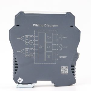
Remarks: 1. Select the function according to the wiring diagram during model selection. Due to the limited number of wiring terminals, only one function can be selected on the same group of terminals.
For example, with 8 -channel input, with 8 transmission outputs, one relay output cannot be provided.
2. The selection must be complete, and the functions that are not selected should also be filled in with codes.
Selection example: DM6210-T31R0T0S-0D-16
5. Operation Instructions
(1) Button function The instrument button is a light touch button, please do not press it hard when using it.
| button | illustrate |
| SET | The parameter setting key, in the setting state, is used to store the new setting value of the parameter and enter the next setting parameter. Press and hold the SET button for about 5 seconds to exit the setting state. |
| ◄ | In the setting state, press this key to shift the corresponding numerical digit, press and hold the ◄ key for about 3 seconds to return to the previous parameter setting.
Press this key to switch the display screen in working state |
| ▲ | The set value increase key is used to increase the value in the setting state. |
| ▼ | The set value reduction key is used to reduce the value in the setting state. |
(2) Parameter setting
In the working state, the instrument display displays the measured values of multiple channels at the same time. In the setting state, the parameter prompt information and set value are displayed. If there is no key operation for about 60 seconds during the setting process, it will automatically return to running. After setting a parameter, press the SET key again to confirm and enter the next parameter setting state.
| serial number | parameter | illustrate |
| 01 | enter password | After setting the password to 808, press the SET key to confirm to enter the parameter setting state. |
| 02 | mailing address | Communication address, range from 1 to 99. |
| 03 | baud rate | The baud rate of communication, ranging from 12.0 to 57.60K bps. |
| 04 | Check Digit | Communication parity bit, no parity none, even parity even, odd parity odd. |
| 05 | Open communication value | When the input signal is not connected to the meter to display the -HH-open state, the value of the communication measurement value is recommended to be set to a value outside the measurement value range such as -300 to distinguish the judgment. |
| 06 | Cycle display time | The liquid crystal display screen of the instrument displays at most 8 channel values at a time, and if more than 8 channels are exceeded, it will be automatically displayed in a loop, the unit is second. |
| 07 | Number of measurement channels | Set the number of input channels of the instrument, the range is 1-16. |
| 08 | filter damping | Measured value filter damping coefficient, range 0-20. The larger the value, the more stable the measurement and the slower the response. The factory default is 0. |
| 09 | temperature compensation correction | When the thermocouple is input, the instrument compensates the temperature error correction, the range is -20.0~20.0. The factory default is 0.0. |
| 10 | Transmission output method | Output V can be set to 0-5V, 1-5V, 0-10. Output mA can be set to 0-20mA, 4-20mA, 0-10mA |
| 11 | AL1 alarm mode | The first relay alarm mode. Setting it to upper limit alarm means that the measured value is over-high alarm, setting it to lower limit alarm means that the measurement value is over-low alarm, and setting it to close the alarm means that the alarm is prohibited at this point. (Alarm refer to “Alarm Description”) |
| 12 | AL2 alarm mode | The second relay alarm mode. |
| 13 | set channel | Set the parameters of a certain channel, for example, you need to set the parameter of the third channel to 3 and then press the SET key to confirm. |
| 14 | Channel 01 input signal | Set the input signal type of the current channel, such as 4-20mA, PT100, etc. See the input signal type comparison table. |
| 15 | Channel 01 decimal point | Set the decimal point position of the current channel, the range is 0~3 |
| 16 | Channel 01 lower range limit | Set the lower limit of the range of the current channel, the range is -9999~9999. |
| 17 | The upper limit of the range of channel 01 | Set the upper limit of the range of the current channel, the range is -9999~9999. |
| 18 | Channel 01 transmission lower limit | Set the transmission lower limit of the current channel, the range is -9999~9999. |
| 19 | Channel 01 transmission upper limit | Set the transmission upper limit of the current channel, the range is -9999~9999. |
| 20 | Channel 01 Zero Correction | Set the zero point error correction value of the current channel. The correction value range is ±99.9, and the factory default is set to 0. Setting it to 99.9 means that the channel does not participate in the measurement. |
| twenty one | Channel 01 full scale correction | Set the full-scale error correction value of the current channel. The correction value range is 0.500~2.000, and the factory default is set to 1.000. Displayed value = full scale correction × (actual measured value + zero point correction). |
| twenty two | Channel 01
AL1 alarm value |
Set the alarm value of the upper limit alarm point of the current channel, the range is -9999~9999. |
| twenty three | Channel 01
AL1 reset value |
Set the alarm reset value of the alarm point on the current channel, the range is -9999~9999. |
| twenty four | Channel 01
AL2 alarm value |
Set the current channel lower limit alarm point alarm value, the range is -9999~9999. |
| 25 | Channel 01
AL2 reset value |
Set the alarm reset value of the current channel lower limit alarm point, the range is -9999~9999. |
| 26 | Copy channel parameters | When set to “Yes”, the parameter values of the current channel’s 13-16, 18-21 items will be copied to all subsequent channels, and the setting state will be exited, reducing the steps of setting the same parameters for each channel. Set to “No” to not copy, jump to item 11 to select the next channel for setting. |
| When the parameter setting is over, -End is displayed, and the instrument automatically enters the running state. | ||
| Input signal type comparison table | |||||
| parameter prompt | signal type | parameter prompt | signal type | parameter prompt | signal type |
| P100 | Pt100 thermal resistance | tC-E | Type E thermocouple | 1-5V | DC1-5V |
| C100 | Cu100 thermal resistance | tC-b | Type B thermocouple | 0-5V | DC0-5V |
| Cu50 | Cu50 thermal resistance | tC-t | T -type thermocouple | 0-10V | DC0-10V |
| bA1 | BA1 thermal resistance | tC-n | Type N thermocouple | 0-50 | 0-50mV |
| bA2 | BA2 thermal resistance | tC-J | Type J thermocouple | 0-100 | 0-100mV |
| rtd | Resistance 0-400Ω | 4-20 | DC4-20mA | Please specify other input signals when ordering | |
| tC-S | Type S thermocouple | 0-10A | DC0-10mA | ||
| tC-K | Type K thermocouple | 0-20 | DC0-20mA | ||
6. Alarm description
The instrument can carry multiple relays, and the channel has two sets of alarm points, which can be set to set the upper limit, lower limit, and close the alarm mode, and the method of setting the alarm reset value is adopted to avoid the frequent action of the relay. When a relay is in an alarm state, the corresponding relay normally open contact is closed, and the corresponding indicator light is on.
7. Quality Assurance
If it is a manufacturer’s manufacturing quality problem, the manufacturer will repair it free of charge from the date of delivery of the instrument. If the damage is caused by improper storage and use, the cost will be charged for repair. Eighteen months warranty.
Product supplied is 1 x DM6210 8 channel input with 8 relay output and rs485 24vdc PT100
Additional information
| Weight | 1000 g |
|---|---|
| Dimensions | 200 × 180 × 110 mm |
Only logged in customers who have purchased this product may leave a review.


Reviews
There are no reviews yet.