

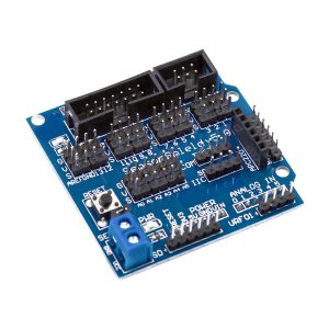
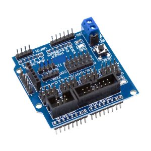
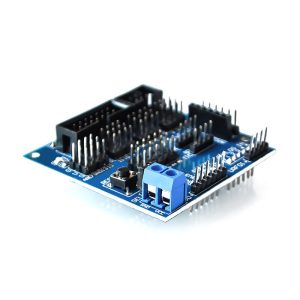
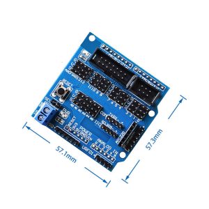
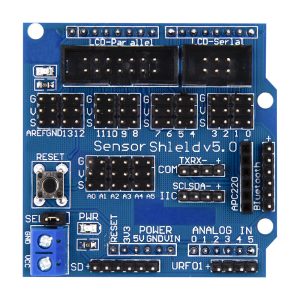
Sensor Expansion Shield V5.0 for Arduino Uno MEGA Servo Module Board
$11.50 Inc. GST
You save (%)
- Description
- Code Examples
- Additional information
- Reviews (0)
Description
🧩 Sensor Expansion Shield V5.0 for Arduino Uno & MEGA – Stackable I/O & Servo Expansion Board | AuscomTech
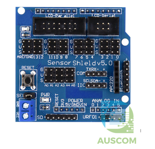
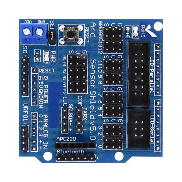
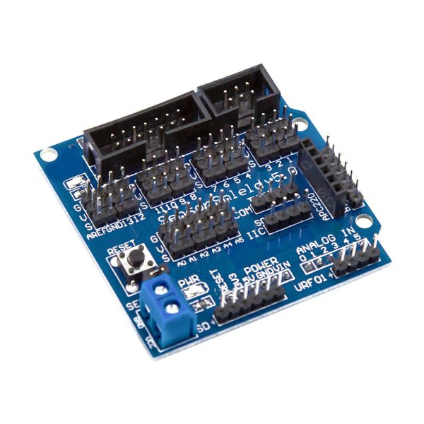
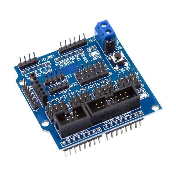
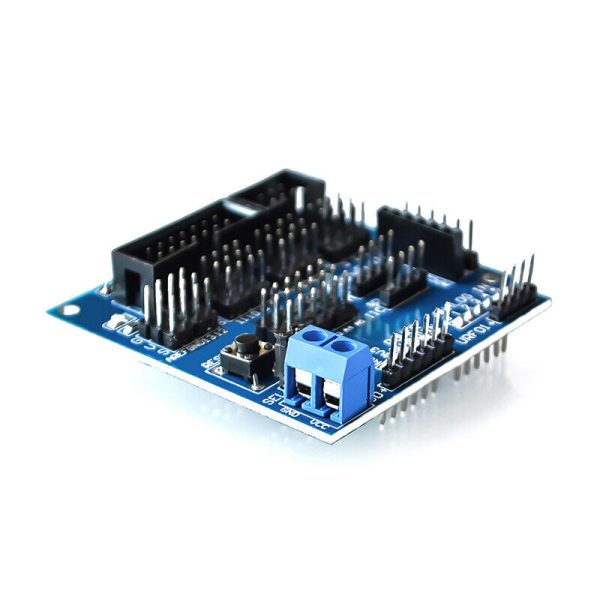
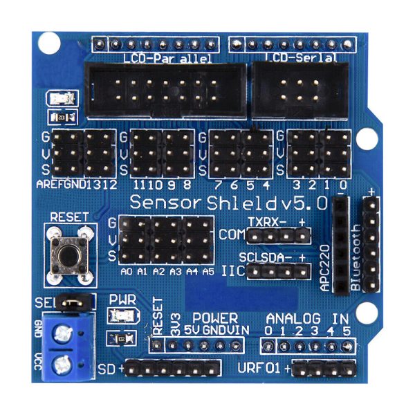
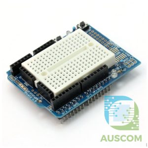
The Sensor Expansion Shield V5.0 is a practical and beginner-friendly I/O expansion board designed to simplify connecting sensors, modules, and servo motors to Arduino development boards.
By converting Arduino pin headers into easy-access 3-pin interfaces (Signal / VCC / GND), this shield dramatically reduces wiring complexity and speeds up prototyping.
Its stackable design allows it to be used alongside other Arduino shields, making it ideal for robotics, automation, and modular electronics projects.
⭐ Key Features
🔌 Plug-and-Play Sensor Connections
Each I/O pin is broken out into a standard 3-pin header, allowing direct connection of common sensor modules without jumper wire confusion.
🧱 Stackable Shield Design
Fully stackable with other Arduino shields for multi-layer project builds.
🦾 Direct Servo Motor Support
Provides dedicated 3-pin headers suitable for standard RC servo motors used in robotics and motion projects.
🧠 Optimised Pin Layout
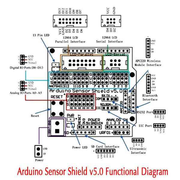
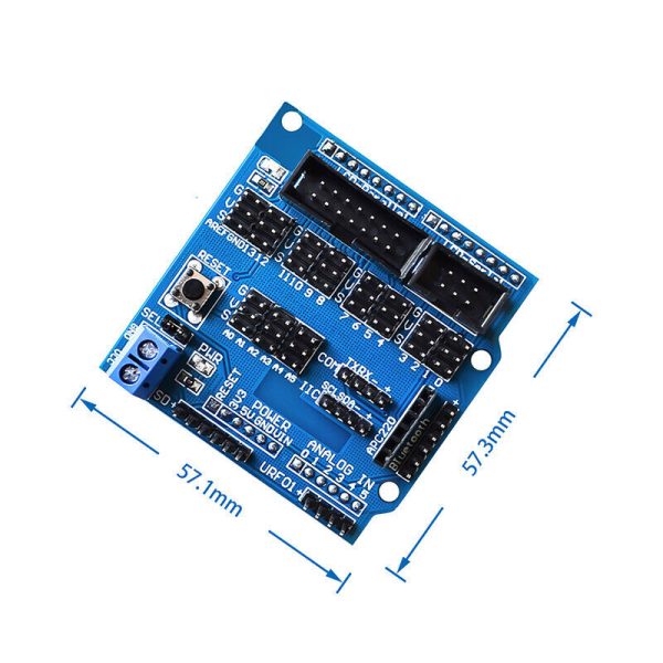
Digital and analog pins are arranged clearly to match Arduino pin numbering for quick identification.
🛠️ Durable PCB Construction
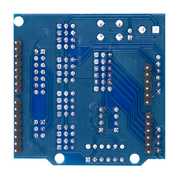
Manufactured with solid PCB material for reliable connections and long-term use.
🔄 Beginner & Education Friendly
Ideal for students, STEM education, rapid prototyping, and hobby electronics.
📊 Technical Specifications
| Specification | Details |
|---|---|
| Product Version | Sensor Expansion Shield V5.0 |
| Compatible Boards | Arduino Uno, Arduino MEGA (pin compatible) |
| Interface Type | 3-Pin (Signal / VCC / GND) |
| Servo Support | Yes (direct connection) |
| Stackable | Yes |
| Material | PCB + plastic headers |
| Colour | Blue / Silver |
| Weight | ~30 g |
🧩 Compatible With
• Arduino Uno
• Arduino MEGA
• Common Arduino sensor modules
• RC servo motors
• Ultrasonic, IR, temperature, humidity sensors
• Robotics and automation modules
🔧 Typical Applications
• Robotics and smart car projects
• Servo-based motion control
• Sensor testing and prototyping
• STEM education kits
• Home automation experiments
• Rapid Arduino project development
⚠️ Usage Notes
• Uses Arduino’s onboard power rails — ensure power limits are not exceeded
• Suitable for low-current sensors and servo motors
• External power recommended for multiple or high-load servos
📦 Package Includes
• 1 × Sensor Expansion Shield V5.0 for Arduino
📌 Code Examples & Usage – Sensor Shield V5.0 (Arduino Expansion Board)
📋 Overview
The Sensor Shield V5.0 provides:
-
Multiple servo headers (GND, VCC, PWM)
-
Digital I/O expansion
-
Analog input expansion
-
Power rail terminals
-
Standard Grove / 3-pin 3.3/5V compatible sockets
This makes it ideal for:
✔ Robot kits
✔ Arduino Uno / Mega I/O expansion
✔ Plug-and-play sensor prototyping
✔ Servo control for arms, wheels, gimbals
It does not change how you code — it simply makes wiring easy.
🔌 Hardware: Pin Mappings
Servo Headers
Each header has:
-
GND
-
VCC (5 V or 3.3 V depending on jumper selection)
-
SIG (PWM / signal)
You can plug servos directly onto these headers.
Sensor Ports
Each port typically gives you:
-
Digital — D2, D3, D4, etc.
-
Analog — A0, A1, A2, etc.
-
Power — 5 V / 3.3 V and GND
Tip: M shield labels are usually famous for being consistent across boards.
🧪 Example 1 — Connect & Sweep a Servo
Wiring:
Sensor Shield → Servo Motor → Plug into Servo1 header
Servo signal pin goes to the shield’s PWM pin (e.g., D9).
🧪 Example 2 — Read an Analog Sensor (e.g., Potentiometer)
Wiring:
Pot → A0 port on Sensor Shield
(gives 0–5 V analog reading)
🧪 Example 3 — Digital Read from a Button
Wiring:
Pushbutton → Digital port (e.g., D2)
Pull-down resistor or use INPUT_PULLUP
🧪 Example 4 — Digital Output (LED)
Wiring:
LED + resistor → D3 on Sensor Shield
⚡ Example 5 — I²C Device (e.g., OLED Display)
If your shield brings out SDA / SCL (many do), you can use I²C displays and sensors.
🧠 Quick Pin Reference (Typical)
| Shield Label | Arduino Pin |
|---|---|
| D2 | Digital 2 |
| D3 | Digital 3 |
| D4 | Digital 4 |
| D5 | Digital 5 |
| A0 | Analog 0 |
| A1 | Analog 1 |
| A2 | Analog 2 |
| SDA / SCL | I²C bus (A4/A5 on Uno, SDA/SCL on Mega) |
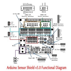
(Your actual shield may label slightly differently — a pinout diagram helps!)
🧠 Notes & Best Practices
✔ Jumper selection: Many Sensor Shields have jumpers to switch servo power between 5 V and 3.3 V — match your device.
✔ Servo current: Standard servos can draw >500 mA — use a separate 5 V supply and common ground with Arduino.
✔ I²C bus: You can chain I²C sensors & displays — make sure addresses don’t clash.
✔ Shield stacking: This board is stackable, but keep sensor lines short to reduce noise.
Additional information
| Weight | 50 g |
|---|---|
| Dimensions | 260 × 160 × 20 mm |
Only logged in customers who have purchased this product may leave a review.
















Reviews
There are no reviews yet.