
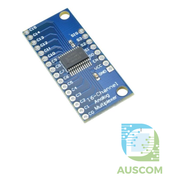
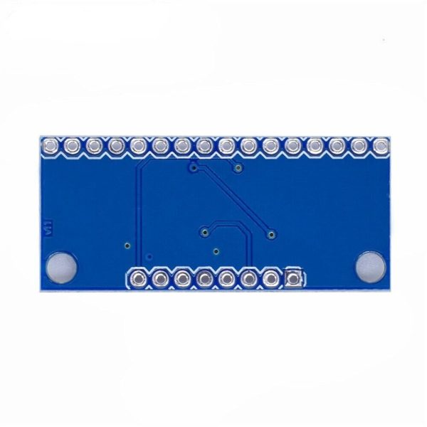
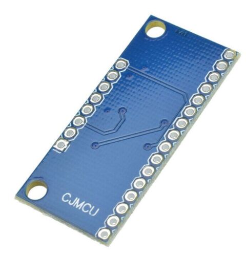
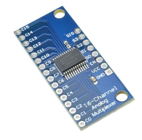
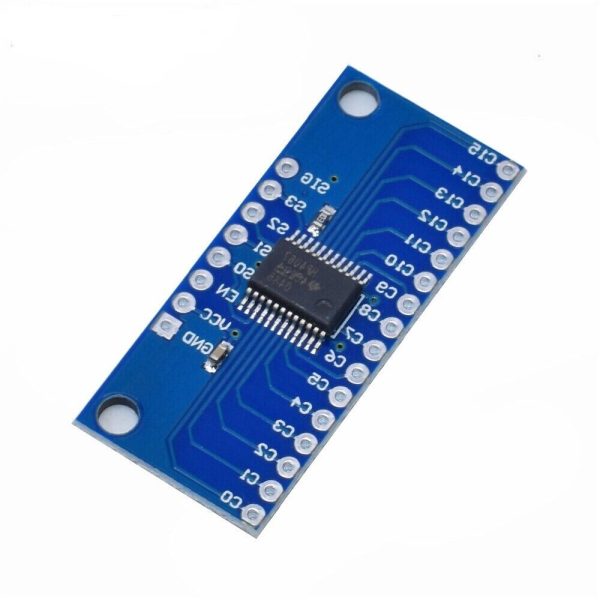
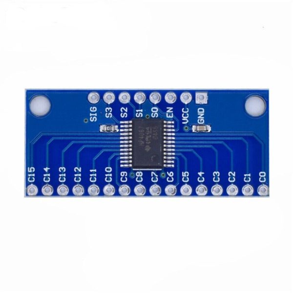
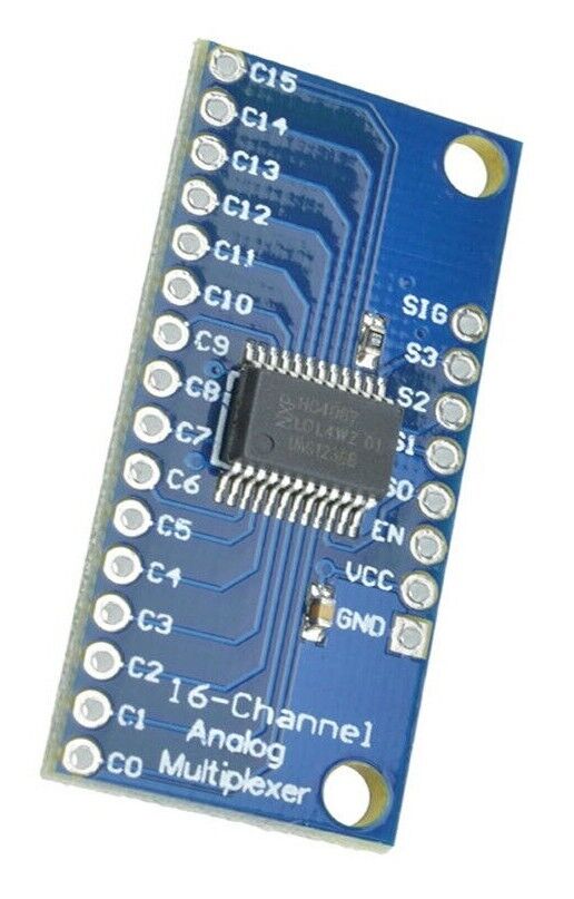
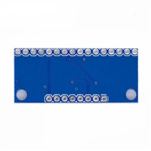
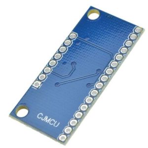
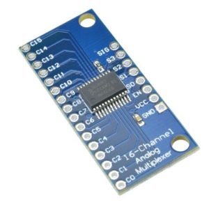
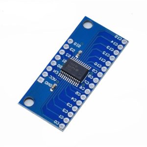
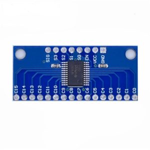
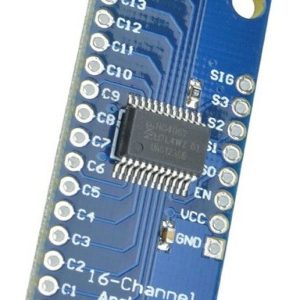
CD74HC4067 16 Channel Analog Digital Multiplexer Module Arduino
$4.75 Inc. GST
You save
- Description
- Code Examples
- Additional information
- Reviews (0)
Description
🧠 CD74HC4067 16-Channel Analog/Digital Multiplexer Module | Arduino & Raspberry Pi | AuscomTech
The CD74HC4067 16-Channel Multiplexer Module is a versatile CMOS-based analog and digital signal switch designed to dramatically expand I/O capability on microcontrollers using only a few control pins.
It allows up to 16 independent signals to be routed through a single common channel, making it ideal for sensor arrays, data acquisition, signal routing, and embedded control systems.
Widely used with Arduino, Raspberry Pi, ESP32, ESP8266, and STM32 platforms, this module simplifies wiring while maintaining reliable, high-speed signal switching.
⭐ Key Features
🔀 16-Channel Signal Multiplexing
Route one of 16 inputs/outputs through a single common pin (SIG) using binary addressing.
⚡ Analog & Digital Signal Support
Handles both analog voltages and digital logic levels, suitable for ADC inputs, GPIO expansion, and signal selection.
🔢 4-Pin Binary Channel Selection (S0–S3)
Select any channel using just four GPIO pins, significantly reducing I/O usage.
🛑 Enable / Disable Control (EN Pin)
Disconnects all channels when disabled, providing full control over signal flow.
⚙️ Wide Operating Voltage Range
Operates from 2V to 6V, compatible with 3.3V and 5V logic systems.
🚀 Fast Switching Performance
Typical switching time of ~6ns at 4.5V with break-before-make action to minimise crosstalk.
🔁 Bidirectional Operation
Signals can flow in either direction, allowing flexible input or output configurations.
📊 Technical Specifications
| Specification | Details |
|---|---|
| IC | CD74HC4067 |
| Channels | 16 |
| Signal Type | Analog & Digital (bidirectional) |
| Operating Voltage | 2V – 6V |
| Logic Level | 3.3V / 5V compatible |
| Control Pins | S0, S1, S2, S3 |
| Enable Pin | EN (active LOW) |
| Switching Time | ~6ns @ 4.5V |
| On-Resistance | Low (CMOS) |
| Break-Before-Make | Yes |
| Board Type | Breakout module |
🧩 Compatible With
• Arduino (Uno, Nano, Mega)
• Raspberry Pi (GPIO / ADC via external ADC)
• ESP32 / ESP8266
• STM32 microcontrollers
• RP2040
• External ADC modules (ADS1115, MCP3008, etc.)
🔧 Typical Applications
• Sensor arrays (temperature, light, pressure, etc.)
• Expanding analog inputs on microcontrollers
• Audio signal routing
• Data acquisition systems
• Robotics & automation
• GPIO expansion
• Signal testing and switching
⚠️ Programming & Wiring Notes
• Only one channel is active at a time
• EN pin must be LOW to enable switching
• Analog signal voltage must remain within VCC and GND
• Ideal for use with external ADCs on platforms with limited analog inputs
📦 Package Includes
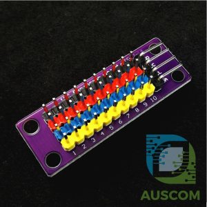
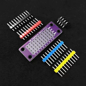
• 1 × CD74HC4067 16-Channel Analog/Digital Multiplexer Module
📌 Code Examples & Usage – CD74HC4067 16-Channel Analog/Digital Multiplexer
📋 Overview
The CD74HC4067 is a 16-channel multiplexer / demultiplexer. It lets a microcontroller connect to one of 16 signals using only 4 select pins.
Great for:
-
Reading lots of analog sensors using one ADC pin
-
Expanding digital inputs (buttons, switches)
-
Sensor arrays (pots, LDRs, moisture probes, etc.)
-
Projects where you run out of ADC pins
It works with both analog and digital signals.
🔌 Pin Basics
Control Pins (Select)
-
S0, S1, S2, S3 = select which channel is active (0–15)
Signal Pins
-
COM / SIG / Z = the common pin (connect this to your MCU input/output)
-
C0–C15 = the 16 channels you switch between
Enable
-
EN (Enable) is usually active LOW
-
EN = LOW → enabled
-
EN = HIGH → disabled (all channels off)
-
⚠ Voltage & Logic Notes
-
Module is usually powered from VCC = 3.3V or 5V
-
Signal range must stay between GND and VCC
-
ESP32 ADC is 0–3.3V only → don’t feed 5V analog signals into ESP32 ADC
-
The multiplexer adds a small resistance (on-resistance), so super high-precision readings may need calibration
🔌 Typical Wiring (Analog Inputs)
Arduino UNO Example
-
VCC → 5V
-
GND → GND
-
EN → GND (always enabled)
-
S0,S1,S2,S3 → D2,D3,D4,D5
-
SIG/COM → A0
-
Sensors → C0..C15
ESP32 Example
-
VCC → 3.3V
-
SIG/COM → ADC pin (e.g. GPIO34)
🧪 1️⃣ Arduino Example – Read All 16 Analog Channels
🧪 2️⃣ ESP32 Example – Read All 16 Analog Channels (0–3.3V)
🧪 3️⃣ Digital Inputs Example – 16 Buttons on One Pin
If you add pull-ups/pull-downs correctly, you can read many buttons/switches too.
🧠 Tips & Troubleshooting
-
If readings are “jumpy”, add:
-
a short settle delay after switching channels (50–200 µs)
-
a small capacitor (e.g. 100nF) from SIG to GND (helps smoothing)
-
-
Keep wires short for analog sensors
-
Don’t exceed VCC on any channel input
-
For best accuracy, do two reads after switching and discard the first read
Example trick:
Additional information
| Weight | 30 g |
|---|---|
| Dimensions | 260 × 160 × 20 mm |
Only logged in customers who have purchased this product may leave a review.












Reviews
There are no reviews yet.