
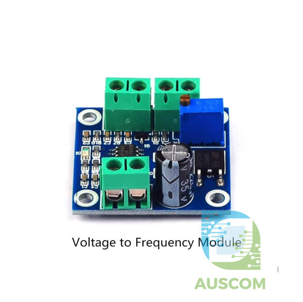
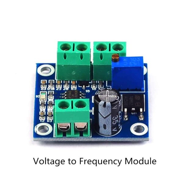
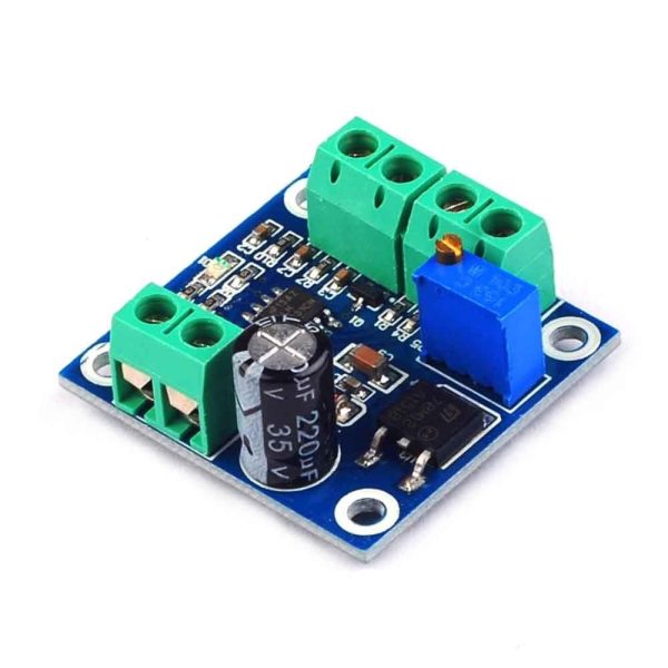
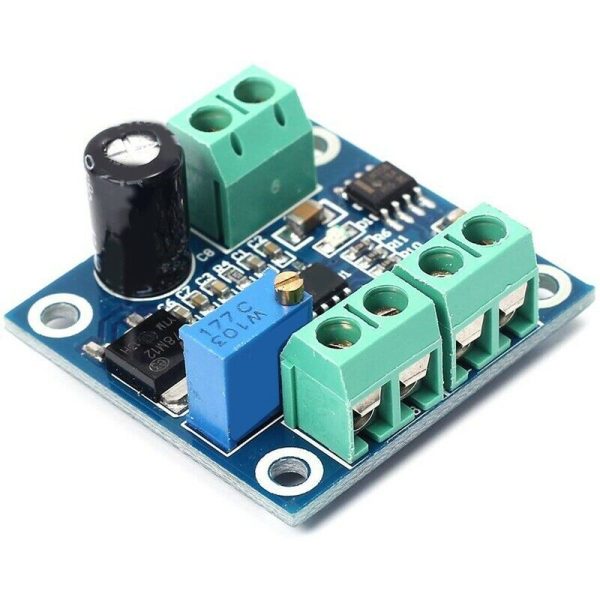
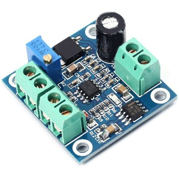
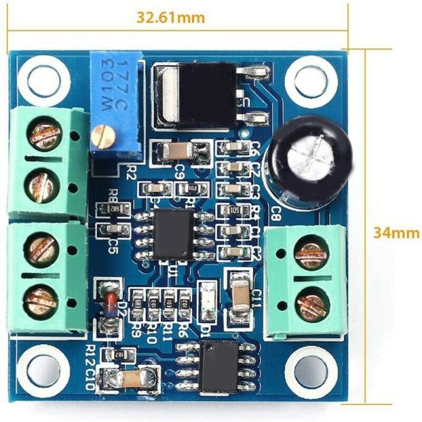
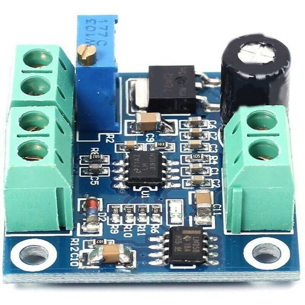
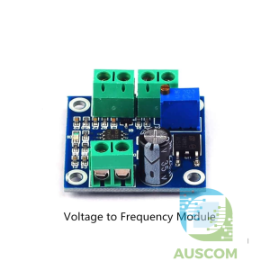
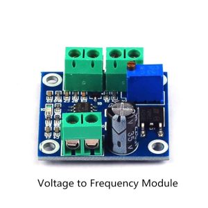
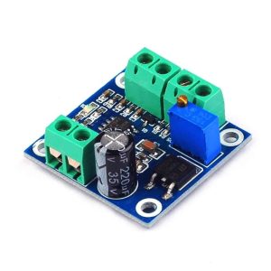
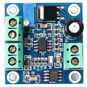
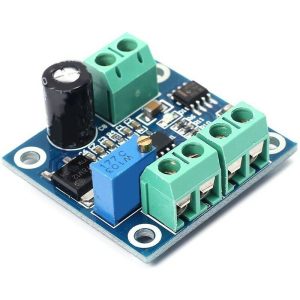
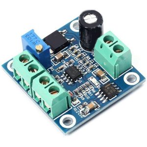
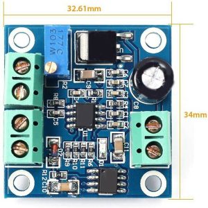
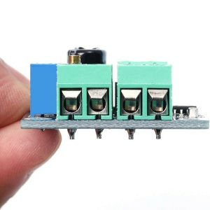
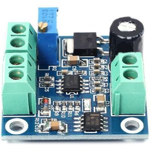
Voltage to PWM Converter Module 0 -10V to 0%-100% Analog to Digital Signal

$16.45 Inc. GST
You save
- Description
- Code Examples
- Additional information
- Reviews (0)
Description
Introducing the LC Voltage to PWM Converter Module: Achieve Precision Control Effortlessly!
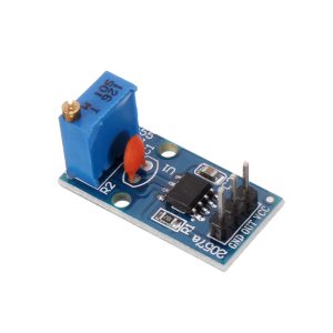
Unlock precision control with our advanced Voltage to PWM Converter Module, an ingenious solution for transforming voltage signals into dynamic PWM outputs. Whether you’re seeking a seamless 0-5V transition or a broader 0-10V spectrum, this module empowers you to effortlessly manipulate PWM duty cycles within the 0% to 100% range. Designed to cater to diverse applications, from motor control to various PWM-dependent scenarios, this compact module guarantees hassle-free integration and operation.
Key Features:
- Seamlessly convert 0-5V or 0-10V voltages into adjustable PWM outputs.
- Utilize voltage adjustments to finely tune PWM duty cycles according to your precise needs.
- Incorporates MCU embedded technology for seamless and efficient performance.
- User-friendly operation with easy-to-access fine-tuning potentiometer.
- Flexible input voltage range selection through short-circuit (jumper) configurations.
- Compact and portable design for seamless integration across a variety of setups.
- Wide working voltage range: DC 5V to 12V, providing versatile power supply options.
- Conversion range of 0V-5V / 0V-10V for comprehensive voltage-to-PWM transformations.
- Ensures exceptional accuracy with a permissible error margin of just 1% – 3%.
- Frequency output upto 50khz
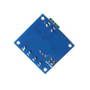
Hardware Interface:
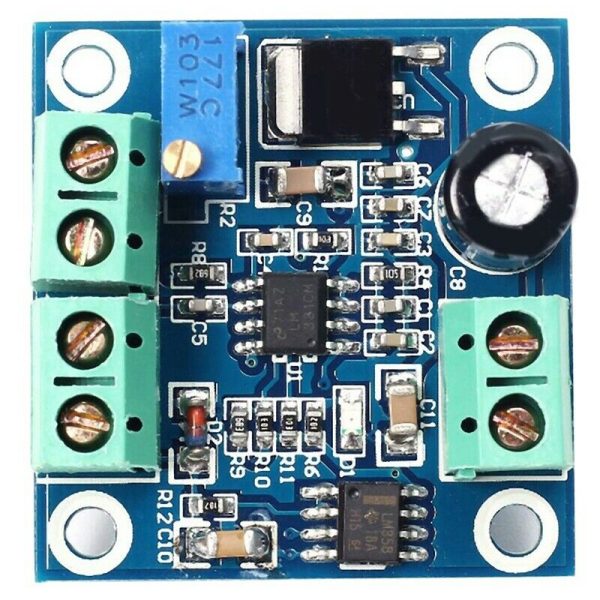
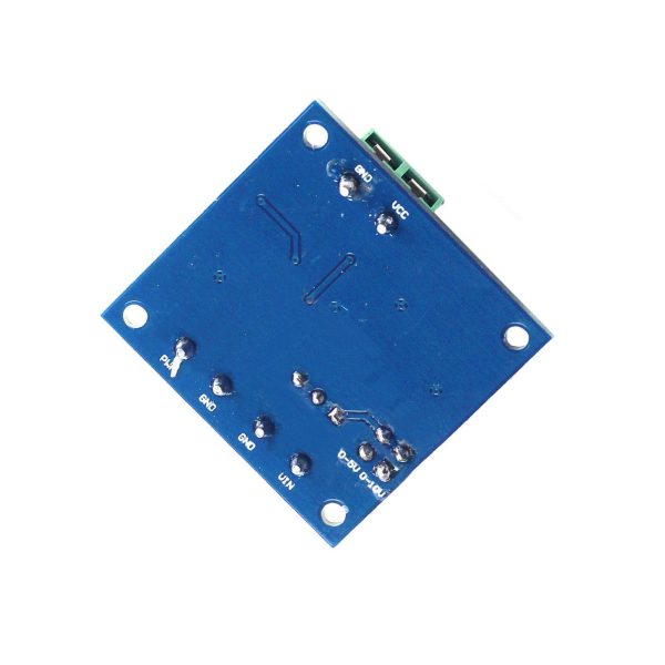
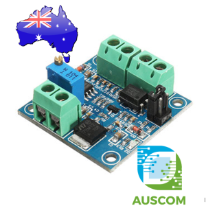
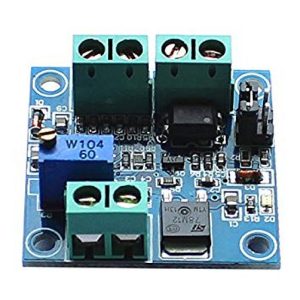
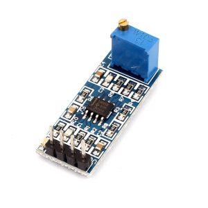
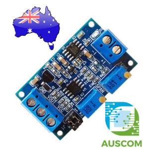
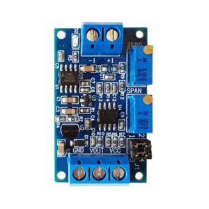
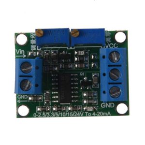
- VCC: Power supply input (5V to 12V) for seamless module operation.
- GND (Power): Ground connection for stable functionality.
- VIN: Input for voltage signals ranging from 0V to 10V.
- GND (Voltage): Ground connection for the input voltage.
- GND (PWM): Ground connection for the PWM output.
- PWM: Output terminal for the transformed PWM signal.
Effortless Operation:
- Safely connect VCC and GND, ensuring correct polarity to prevent any damage.
- Input voltage via VIN adhering to the selected mode (0-5V or 0-10V).
- Observe the PWM output, reflecting the PWM signal obtained from the input voltage.
- Harness the power of voltage adjustments to achieve desired PWM duty ratios.
- Fine-tune with precision using the integrated potentiometer to control output accuracy.
Upgrade your control mechanisms with the LC Voltage to PWM Converter Module. Empower yourself with precision, flexibility, and seamless integration. Whether you’re a motor control enthusiast or seeking precise PWM control, this module is your gateway to optimized performance. Elevate your voltage-to-PWM transformations with our game-changing solution – order now!
📌 Code Examples & Usage – 0–10V to PWM Converter Module
📋 Overview
This module converts a 0–10V analog control signal into a PWM (Pulse Width Modulation) output, making it ideal for interfacing industrial control signals with:
-
Microcontrollers (Arduino / ESP32)
-
PWM motor controllers
-
LED dimmers
-
VFD control inputs
-
PLC or building automation systems
It allows high-voltage analog signals to be safely translated into a logic-level PWM signal.
⚙ Key Features
-
Input voltage range: 0–10 V DC
-
Output signal: PWM (0–100% duty cycle)
-
Adjustable gain & scaling (onboard potentiometer)
-
Electrical isolation (varies by module version)
-
Stable, noise-resistant design
-
Industrial screw terminals
🔌 Typical Pinout
Input Side (Analog Voltage)
| Terminal | Function |
|---|---|
| VIN+ | 0–10V signal |
| VIN- | Signal ground |
Output Side (PWM)
| Pin | Function |
|---|---|
| PWM OUT | PWM signal |
| GND | Ground |
| VCC | Module power (typically 5V or 12V – check board marking) |
📌 Important:
The PWM output is logic-level, not a power output.
⚠ Important Safety Notes
-
Do NOT exceed 10V input
-
Ensure grounds are correctly referenced
-
Do not connect PWM output directly to high-power loads
-
Use proper isolation when connecting to PLC or industrial systems
-
Always confirm module supply voltage (some versions require 12V)
🔄 How It Works (Simple Explanation)
| Input Voltage | PWM Output |
|---|---|
| 0 V | 0% duty |
| 2.5 V | ~25% duty |
| 5 V | ~50% duty |
| 7.5 V | ~75% duty |
| 10 V | ~100% duty |
The module continuously converts voltage level into PWM duty cycle.
🧪 1️⃣ Arduino Example – Reading the PWM Output
This example measures the PWM signal and converts it back into a percentage.
✔ Works on Arduino & ESP32
✔ Useful for monitoring industrial 0–10V signals digitally
🧪 2️⃣ ESP32 Example – PWM Monitoring
🧪 3️⃣ Example Use Case – VFD Speed Feedback
-
VFD outputs 0–10V speed reference
-
Converter outputs PWM
-
ESP32 reads PWM and logs speed
-
Data sent via WiFi / MQTT / Modbus
This allows non-invasive monitoring of industrial equipment.
🧪 4️⃣ Example Use Case – LED or Motor Control
-
PLC outputs 0–10V
-
Converter produces PWM
-
PWM drives:
-
MOSFET
-
LED dimmer
-
Motor driver
-
✔ Perfect for bridging PLC → PWM-only devices
🎛 Calibration & Adjustment
Most modules include trimmer potentiometers:
-
Adjust zero point (0V = 0%)
-
Adjust full scale (10V = 100%)
Calibration steps:
-
Apply 0V → adjust until PWM = 0%
-
Apply 10V → adjust until PWM = 100%
🧠 Tips & Best Practices
✔ Use shielded cable for long 0–10V runs
✔ Keep analog and PWM wiring separated
✔ Avoid noisy power supplies
✔ Use optocoupler or isolation for high-EMI environments
✔ Confirm PWM frequency if driving external hardware
Additional information
| Weight | 40 g |
|---|---|
| Dimensions | 260 × 160 × 20 mm |
Only logged in customers who have purchased this product may leave a review.











Reviews
There are no reviews yet.