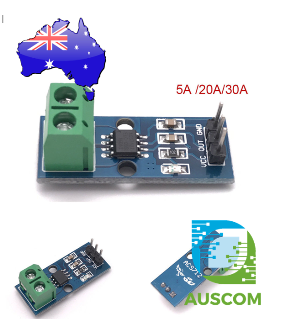
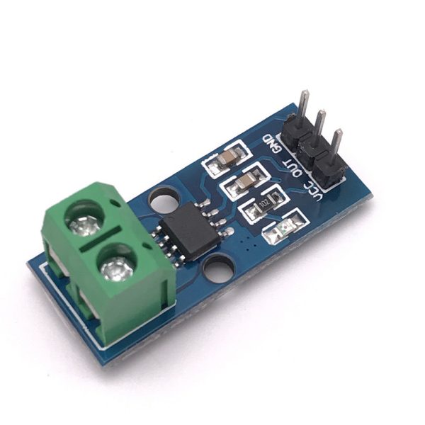
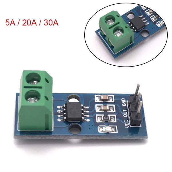
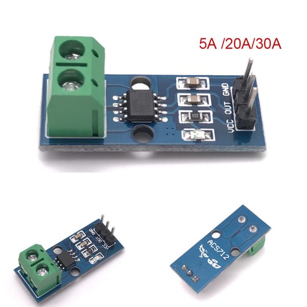
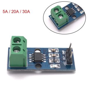
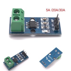
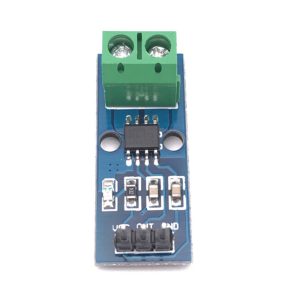
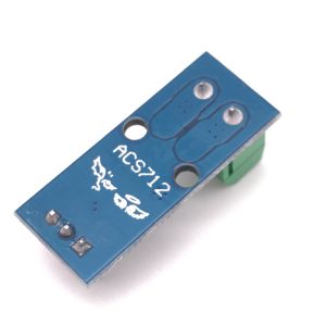
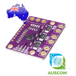
ACS712 Current Sensor Module 5A 20A 30A AC DC Arduino
$6.45 Inc. GST
You save (%)

Description

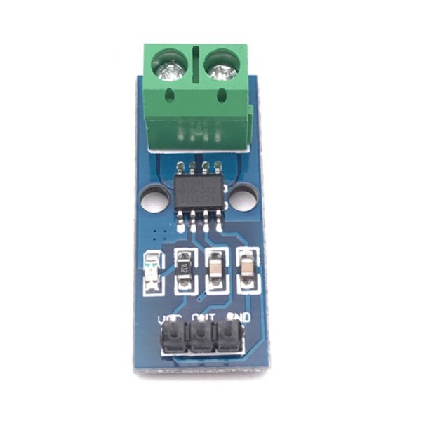
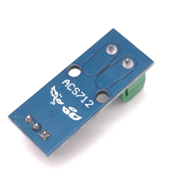
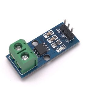
ACS712 Hall Effect Current Sensor Module 5A 20A 30A AC/DC | AuscomTech

The ACS712 Current Sensor Module is a reliable, non-intrusive current sensing solution designed for accurate AC and DC current measurement in electronics, energy monitoring, and automation projects.

Available in 5A, 20A, and 30A variants, this module uses Hall effect sensing to measure current flow without inserting resistance into the circuit, making it ideal for Arduino, Raspberry Pi, and microcontroller-based power monitoring applications.


Key Features

🧲 Hall Effect Current Sensing
Provides isolated, low-loss measurement of AC and DC current without direct electrical contact.

📏 Multiple Current Ranges Available
Choose the correct variant for your application: 5A, 20A, or 30A.

🔁 Bidirectional Measurement
Supports both positive and negative current flow for versatile monitoring.

📊 Analog Voltage Output
Linear voltage output proportional to current for easy ADC reading by microcontrollers.

Stable Zero-Current Output
Output voltage remains centred at VCC / 2 when no current is flowing.

🔌 Microcontroller Friendly
Designed for seamless integration with Arduino, Raspberry Pi (via ADC), ESP32, STM32, and similar platforms.

💡 Onboard Power Indicator LED
Provides visual confirmation that the module is powered and operating.


📊 Technical Specifications

Sensor IC: ACS712
Supply Voltage: 5V DC
Measurement Type: AC & DC current
Isolation: Hall effect (electrically isolated)

5A Module:
• Sensitivity: 185 mV/A
• PCB Size: 31 × 13 mm

20A Module:
• Sensitivity: 100 mV/A
• PCB Size: 27.4 × 11.8 mm

30A Module:
• Sensitivity: 66 mV/A
• PCB Size: 31 × 13 mm

Zero Current Output: VCC / 2
Output Type: Analog voltage
Response Time: <5 µs


⚠️ Important Notes

• Output is analog — requires ADC input on the controller
• Raspberry Pi requires an external ADC module
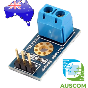
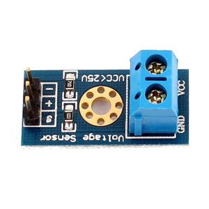
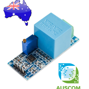
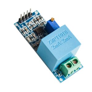
• Terminal block colour may vary (blue or green)
• Proper calibration improves accuracy, especially at low currents


🧩 Compatible With

• Arduino Uno / Mega / Nano
• Raspberry Pi (with ADC)
• ESP32 / ESP8266
• STM32 microcontrollers
• PLC analog input systems
• Energy monitoring systems


⚙️ Typical Applications

• AC/DC power monitoring
• Solar and battery management systems
• Motor current sensing
• Smart energy meters
• Overcurrent detection
• Robotics and automation
• IoT power measurement


📦 Package Includes

• 1 × ACS712 Current Sensor Module (5A, 20A, or 30A – select variant)

📌 Code Examples – ACS712 Current Sensor (5 A / 20 A / 30 A)

📋 Overview

The ACS712 is a Hall-effect based current sensor that outputs a voltage proportional to the current flowing through it. It works for AC and DC and provides:

✔ Electrical isolation between measurement circuit and MCU
✔ Low cost and easy interface
✔ Multiple current ranges: 5 A / 20 A / 30 A

This tab shows how to:

  • Read current on Arduino

  • Read current on ESP32

  • Measure AC RMS current


⚠ Safety & Wiring Notes

Pin Function
VCC 5 V (MCU logic)
GND MCU ground
OUT Analog voltage output

Important

✔ The sensor should be placed in series with the load whose current you’re measuring
✔ The voltage output swings around Vcc/2 (because Hall sensor detects both directions)
✔ For AC measurements, you must compute RMS values over many samples


📈 Theory: How It Works

The sensor outputs:

Vout = Vcc/2 ± (Current × Sensitivity)

Where sensitivity varies by model:

Model Sensitivity (mV/A)
5 A ~185 mV/A
20 A ~100 mV/A
30 A ~66 mV/A

Check your module’s exact datasheet for the correct value!

For example on a 5 A sensor:

  • At 0 A, Vout ≈ 2.5 V

  • At +5 A, Vout ≈ 2.5 V + (5 × 0.185) ≈ 3.425 V

  • At -5 A, Vout ≈ 2.5 V – (5 × 0.185) ≈ 1.575 V


🧪 Arduino Example – DC Current

This example reads the analog voltage and converts it to current (DC).

const int sensorPin = A0; // Analog pin to read
const float Vref = 5.0; // Arduino reference
// Choose the correct sensitivity for your ACS712
const float sensitivity = 0.100; // 100 mV/A for 20A version
void setup() {
Serial.begin(9600);
}

void loop() {
int raw = analogRead(sensorPin); // 0–1023
float voltage = (raw * Vref) / 1023.0;

// Zero current offset (around Vref/2)
float offset = Vref / 2.0;

// Convert voltage to current
float current = (voltage – offset) / sensitivity;

Serial.print(“Voltage: “);
Serial.print(voltage, 3);
Serial.print(” V | Current: “);
Serial.print(current, 3);
Serial.println(” A”);

delay(500);
}

⚠ Replace sensitivity with:

  • 0.185 for ACS712-5A

  • 0.100 for ACS712-20A

  • 0.066 for ACS712-30A


⚡ ESP32 Example – DC Current

ESP32 ADCs are 12-bit (0–4095). Adjust accordingly:

const int sensorPin = 34; // ESP32 ADC pin
const float Vref = 3.3; // ESP32 ADC reference
const float sensitivity = 0.100; // for 20A version
void setup() {
Serial.begin(115200);
analogReadResolution(12); // 0–4095 range
}

void loop() {
int raw = analogRead(sensorPin);
float voltage = (raw * Vref) / 4095.0;
float offset = Vref / 2.0;
float current = (voltage – offset) / sensitivity;

Serial.print(“Voltage: “);
Serial.print(voltage, 3);
Serial.print(” V | Current: “);
Serial.print(current, 3);
Serial.println(” A”);

delay(500);
}


📊 Example – AC Current (RMS Calculation)

AC measurement requires many samples to compute the RMS current:

// RMS current example (Arduino)

const int sensorPin = A0;
const float Vref = 5.0;
const float sensitivity = 0.100; // change per your module

const int numSamples = 2000;

void setup() {
Serial.begin(9600);
}

void loop() {
long sumSquares = 0;
for (int i = 0; i < numSamples; i++) {
int raw = analogRead(sensorPin);
float voltage = (raw * Vref) / 1023.0;
float current = (voltage – (Vref / 2.0)) / sensitivity;
sumSquares += current * current;
delayMicroseconds(100); // approx 10kHz sampling
}

float rms = sqrt(sumSquares / (float)numSamples);

Serial.print(“AC RMS Current: “);
Serial.print(rms, 3);
Serial.println(” A”);

delay(1000);
}

⚠ Sample count and delay affect frequency response — adjust to match the AC frequency you expect.


🧠 Tips & Calibration

✔ Always measure offset (zero current) on your own board — it can vary slightly from Vref/2
✔ For better accuracy, average multiple readings
✔ Use a stable power source to reduce ADC noise
✔ For low current (<1 A) on high-range modules, measurement accuracy is lower

Additional information

Weight 40 g
Dimensions 260 × 160 × 20 mm
Current

5A, 20A, 30A

Reviews

There are no reviews yet.


Only logged in customers who have purchased this product may leave a review.