
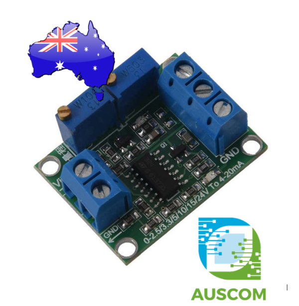
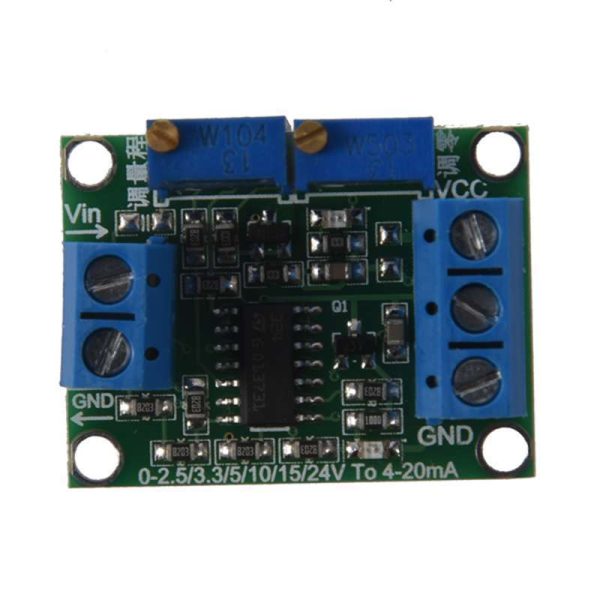
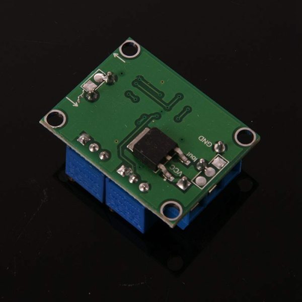
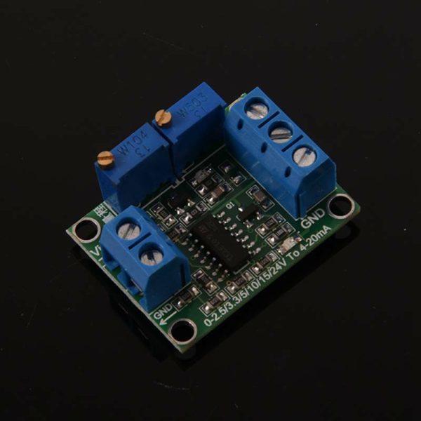
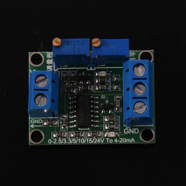
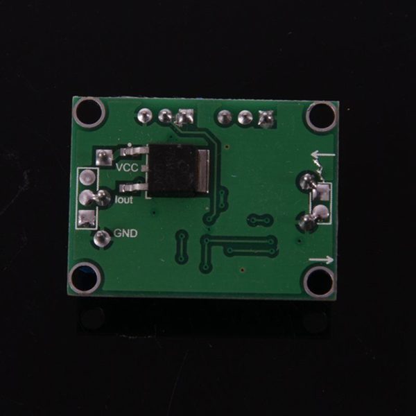
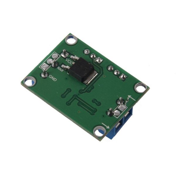
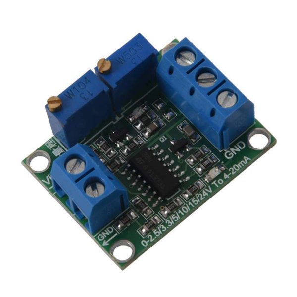
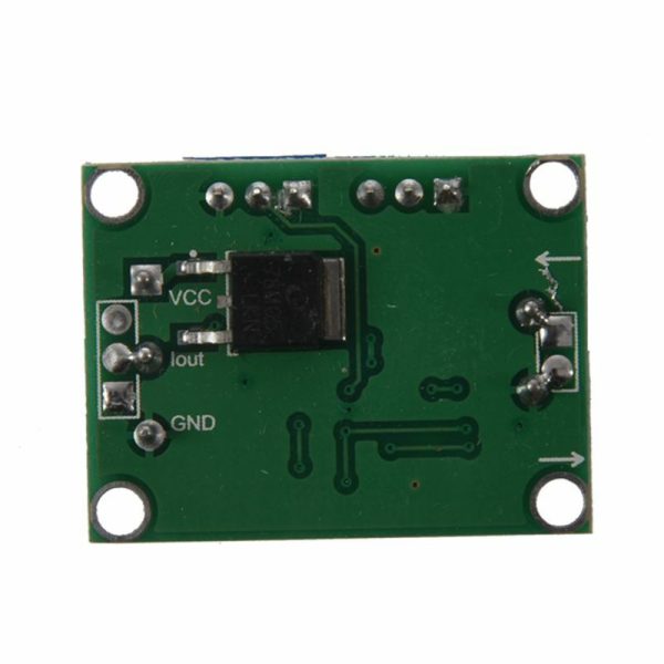
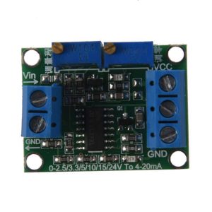
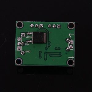
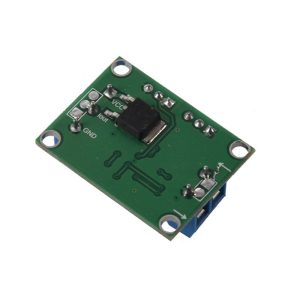
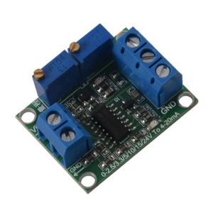
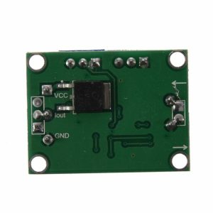
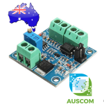
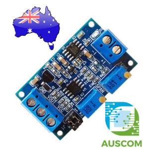
Voltage to Current 0-2.5V/3.3V/5V/10V/15V/24V to 4-20mA Analog Signal Converter Module
$18.40 Inc. GST
You save (%)
- Description
- Code Examples
- Additional information
- Reviews (0)
Description
Enhance Your Signal Conversion with Our Voltage to Current 0-24V to 4-20mA Converter Module
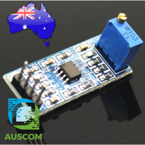
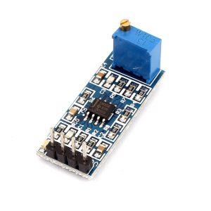
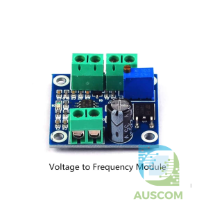
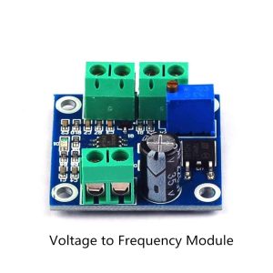
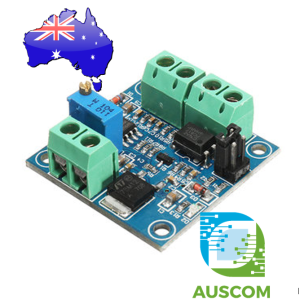
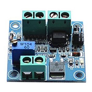
Unlock the potential of precise signal transmission with our advanced Voltage to Current Converter Module. This versatile module is designed to seamlessly transform voltage signals, ranging from 0-2.5V to 24V, into corresponding 4-20mA current signals, ensuring optimal accuracy and reliability throughout your circuit.
Key Features:
- Wide Power Supply Range: Operating flawlessly within a power supply voltage range of 7V to 30VDC, this module adapts to various setups with ease.
- Flexible Voltage Compatibility: Convert voltage signals ranging from 0V to 2.5V, 3.3V, 5V, 10V, 15V, or 24V into precise 4-20mA current outputs.
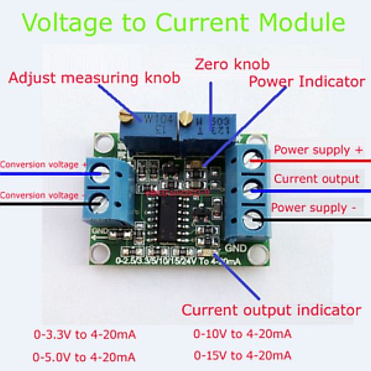
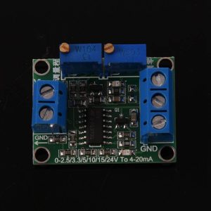
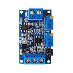
- Customizable Calibration: Fine-tune your signals using the zero and full-scale adjustments, conveniently controlled by potentiometers.
- Enhanced Isolation: Our module ensures reliable performance with non-optocoupler isolation, providing stable signal transmission.
- Compact Design: With dimensions of just 3.3 x 2.5cm, this module offers a space-efficient solution without compromising functionality.
Linear Conversion Equations: Experience a seamless conversion process with the linear relationship between input voltage and output current. Define the relationship using the linear equation Iout = K * V + b, simplifying signal calibration.
Easy-to-Follow Manual:
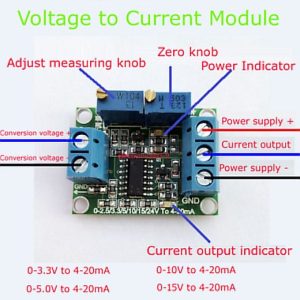
- Installation: Connect the power supply terminals on the module’s right side.
- Zero Adjustment: Reset the output current to 4mA by adjusting the zero potentiometer after setting the conversion voltage to 0V.
- Full-Scale Tuning: Set the desired full-scale voltage (e.g., 3.3V, 5V, 10V, 15V) and adjust the full potentiometer to achieve 20mA output current.
- Precise Adaptation: Within the specified input voltage range, the module provides accurate current output that aligns with your power supply.
Adjustment Example: Imagine you have a 24V supply and want to convert 0-10V to 4-20mA:
- Supply Connection: Connect the positive side of the 24V supply to the right terminal, and the negative side to the corresponding terminal.
- Zero Calibration: Short the left-side terminals and adjust the zero knob to attain a 4mA output.
- Span Adjustment: Configure the left-side voltage to 10V and its negative pole, then adjust the span knob to achieve a 20mA output.
- Dynamic Transformation: Witness seamless linear changes in output current (4-20mA) corresponding to voltage adjustments (0-10V).
Package Contents:
- 1 x Voltage to Current Converter Module
Elevate your signal conversion capabilities with our Voltage to Current Converter Module. Experience precision, versatility, and efficiency in your circuitry like never before. Order now to revolutionize your signal transmission process.
📌 Code Examples & Usage – Voltage to 4–20mA Analog Converter Module
📋 Overview
This module converts a control voltage (such as 0–2.5V / 0–3.3V / 0–5V / 0–10V / 0–15V / 0–24V, depending on model) into an industry-standard 4–20mA current loop signal.
It’s commonly used for interfacing microcontrollers and sensors with:
-
PLC analog inputs (4–20mA)
-
Industrial controllers / SCADA
-
VFD / pump controllers
-
Process instrumentation
-
Long cable runs where voltage signals would be noisy
✅ Why 4–20mA?
A 4–20mA current loop is widely used because:
-
Current is more immune to noise over long cables
-
The “live zero” at 4mA helps detect wiring faults (0mA often indicates a broken loop)
⚙ Key Features
-
Input: voltage (model dependent)
-
Output: 4–20mA current loop
-
Suitable for industrial analog inputs
-
Often includes:
-
Zero (4mA) trim
-
Span (20mA) trim
-
-
Can be driven from:
-
DAC output
-
Filtered PWM
-
Analog control voltage source
-
⚠ IMPORTANT – Read Before Use
✅ This module is not a sensor — it’s a signal converter.
✅ You must provide the correct power supply for the module (often 12–24V depending on design).
✅ The 4–20mA output usually requires a load (like a PLC input or resistor) to measure voltage across.
⚠ If you plan to drive it from Arduino PWM, use a low-pass filter (RC) to create a stable analog voltage.
🔌 Typical Terminals (May Vary by Board)
Most boards have terminals similar to:
Input Side (Voltage)
-
VIN+ / IN+
-
VIN- / IN- (GND)
Power
-
V+ / +24V
-
V- / GND
Output Side (Current Loop)
-
I+ / OUT+
-
I- / OUT-
📌 Some boards combine grounds; always follow the silkscreen labels.
🧪 Quick Bench Test (No PLC Needed)
To test the 4–20mA output with a multimeter:
Option A: Measure current directly
-
Set multimeter to mA
-
Put meter in series with the output loop:
-
Module I+ → Meter → Load/Return → Module I-
-
-
Apply input voltage and verify current changes
Option B: Use a resistor and measure voltage
Use a 250Ω resistor as a loop load:
-
4mA → 1.0V
-
20mA → 5.0V
This is convenient because many PLCs use 250Ω internally.
🧪 Arduino Example – Using PWM + RC Filter (5V Arduino)
If you don’t have a real DAC, you can generate an analog control voltage using PWM.
Hardware Needed
-
PWM pin (e.g. D9)
-
RC low-pass filter:
-
10kΩ resistor in series
-
10µF capacitor to GND
-
Wiring:
-
D9 → 10kΩ → module VIN+
-
VIN+ to GND: 10µF capacitor
-
module VIN- → Arduino GND
📌 The RC filter smooths PWM into a near-DC voltage.
📌 If your module input range is 0–10V, you’ll need a voltage scaler (or use a true DAC + amplifier).
🧪 ESP32 Example – Higher Resolution PWM (LEDC)
ESP32 PWM is higher resolution and smoother after filtering.
🎛 Calibration (Zero & Span)
Most modules have 2 trim pots:
-
ZERO: adjust output at 0V input to exactly 4.00mA
-
SPAN: adjust output at full-scale input to exactly 20.00mA
Recommended Calibration Steps
-
Set input to 0V → adjust ZERO to 4.00mA
-
Set input to full-scale (e.g., 5V or 10V depending on model) → adjust SPAN to 20.00mA
-
Repeat once more (they interact slightly)
🧠 Troubleshooting
| Issue | Cause | Fix |
|---|---|---|
| Output stuck near 4mA | Input not reaching range | Verify input model (0–5V vs 0–10V etc.) |
| Output doesn’t change | Wrong wiring | Confirm VIN+/VIN- and I+/I- |
| No current flow | Open loop / no load | Ensure loop is closed through PLC/load |
| Noisy current | PWM not filtered | Add RC filter / increase capacitor |
| Wrong scaling | Not calibrated | Perform zero/span calibration |
Additional information
| Weight | 30 g |
|---|---|
| Dimensions | 260 × 160 × 20 mm |
Only logged in customers who have purchased this product may leave a review.











Reviews
There are no reviews yet.