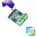
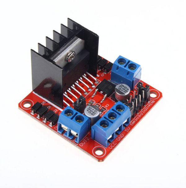
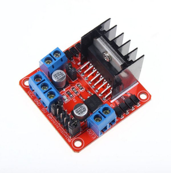
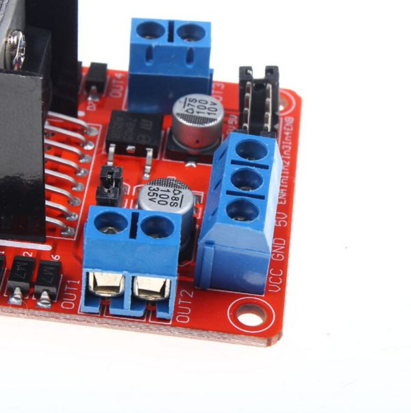
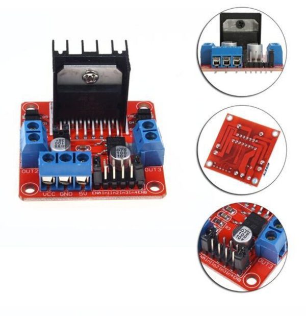
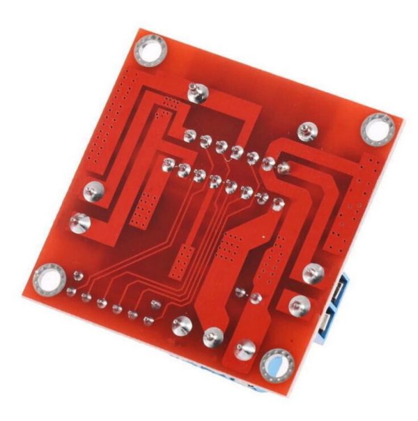
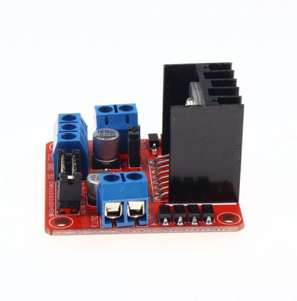
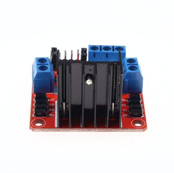
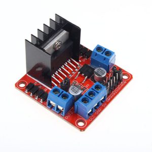
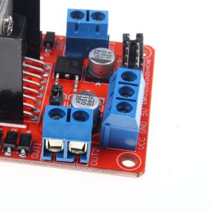
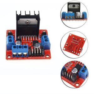
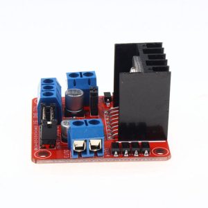
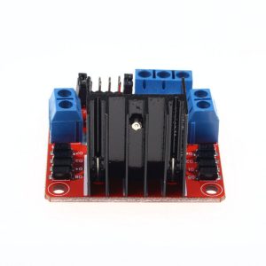
L298N Dual H Bridge Stepper Motor Drive Controller Board Module For Arduino
$10.95 Inc. GST
You save (%)

Availability: 111 in stock SKU: 6-3-3-0 Category:
Quantity Discount (%) Price
1 $10.95
2 - 4 5 % $10.40
5 - 9 7.5 % $10.13
10 - 19 10 % $9.86
20 - 49 12.5 % $9.58
50 - 99 15 % $9.31
100+ 17.5 % $9.03

Description

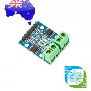
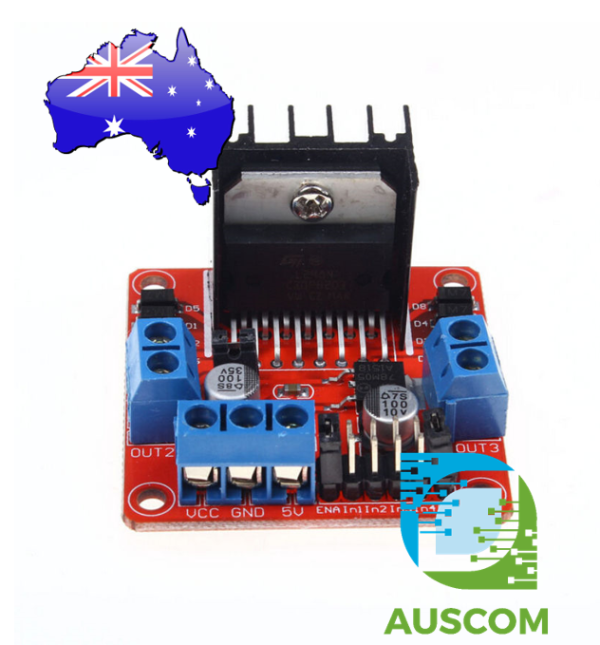
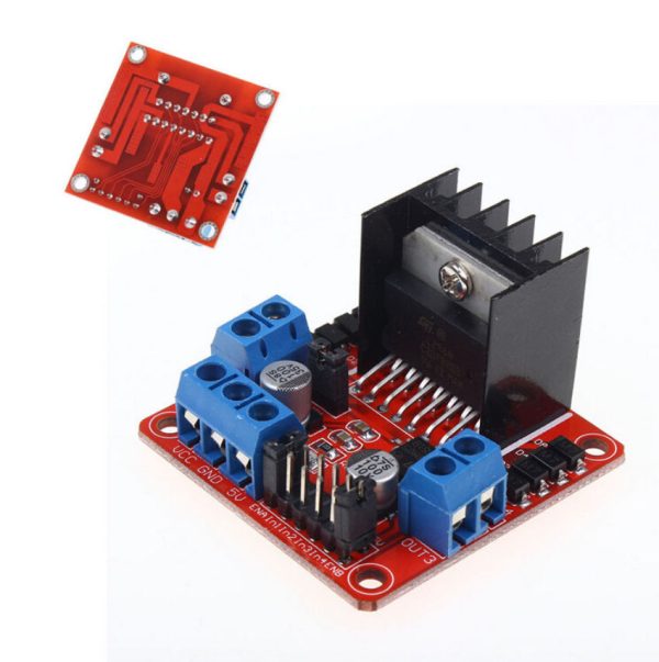
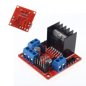
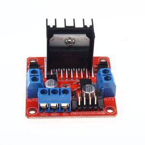
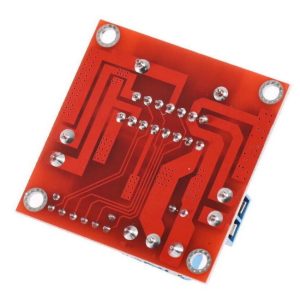
Introducing the L298N Dual H Bridge Stepper Motor Drive Controller Board Module for Arduino. This module harnesses the power of the L298N high voltage, high current motor driver chip, offering exceptional performance and versatility for your motor control needs.

Key Features:

  • High Voltage Capability: With a maximum operating voltage of up to 46V, the L298N chip empowers your projects with enhanced voltage management.
  • Robust Current Handling: Experience peak current handling of up to 3A and a continuous operating current of 2A, supporting reliable and efficient motor control.
  • Versatile Compatibility: Drive a range of devices, from DC motors and stepper motors to relays and inductive loads, thanks to the dual H-bridge high-voltage, high-current full-bridge driver configuration.
  • Logic-Level Control: Easily manage your motor control with standard logic-level signals, simplifying the integration process.
  • Dual Enable Control: Benefit from two enable control terminals that allow uninterrupted input signals, while a logic supply input safeguards against interference.
  • Stepper Motor Expertise: Leverage the power of the L298N chip to effortlessly drive two-phase stepper motors or four-phase stepper motors, as well as two DC motors.
  • Efficient Design: The L298N chip’s design ensures low heat generation, exceptional driving ability, and anti-jamming features, enhancing overall performance.
  • Power Management: The module incorporates a built-in 78M05 drive power segment, offering operational efficiency. For voltages exceeding 12V, an external 5V logic supply is recommended to prevent regulator chip damage.
  • Enhanced Reliability: Equipped with high-capacity filter capacitors and freewheeling diode protection, this module enhances the reliability of your motor control projects.

Application Scenarios: This L298N Dual H Bridge Stepper Motor Drive Controller Board Module finds its utility in a wide array of applications, ranging from robotics and automation to DIY electronics and prototyping.

Note:

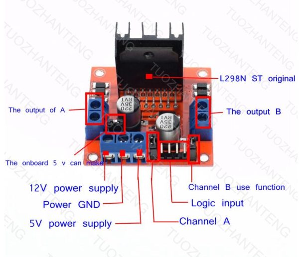
  1. Voltage Range Flexibility: Operating within a voltage range of 7V to 12V, you can employ the onboard 5V logic supply by enabling it. This onboard power is suitable for external 5V use.
  2. Beyond 12V Voltage Use: Should you require a voltage higher than 12V but within 24V, simply disconnect the onboard 5V output enable jumper caps. This facilitates the use of L298N’s internal voltage logic circuitry for unconventional high-voltage motor control applications.

Unlock the potential of precise and efficient motor control with the L298N Dual H Bridge Stepper Motor Drive Controller Board Module. Whether you’re driving stepper motors or managing various loads, this module offers a reliable and adaptable solution for your projects.

📌 Code Examples & Usage – L298N Dual H-Bridge Motor Driver Module

📋 Overview

The L298N motor driver module is a dual H-bridge controller used to drive:

  • 2 × DC motors (forward/reverse + speed control)

  • 1 × bipolar stepper motor (basic stepping sequences)

It’s popular for Arduino and robotics projects thanks to simple wiring and onboard screw terminals.

Common applications:

  • Robot cars and tracked robots

  • Small pumps / fans / actuators

  • Basic stepper motor control projects

  • Prototyping motor control systems


⚙ Key Features

  • Driver IC: L298N

  • Channels: 2 H-bridges (Motor A + Motor B)

  • Motor supply: ~6V to 35V (module dependent)

  • Logic supply: 5V

  • Control: IN1–IN4 + ENA/ENB (PWM capable)

  • Onboard 5V regulator (some boards) + heatsink


⚠ IMPORTANT – Performance Notes (Read This)

✅ Voltage Drop

The L298N uses older bipolar transistors, so it has a significant voltage drop (often ~2V or more under load).

Example:
If you supply 12V, the motor may only see ~10V (or less).

✅ Heat

Because of the voltage drop, the driver can get hot under load.
Use the heatsink and allow airflow.

✅ Best Use

✔ Great for small/medium brushed DC motors
✔ OK for basic steppers at low current
❌ Not ideal for high-efficiency battery builds (use TB6612 instead)


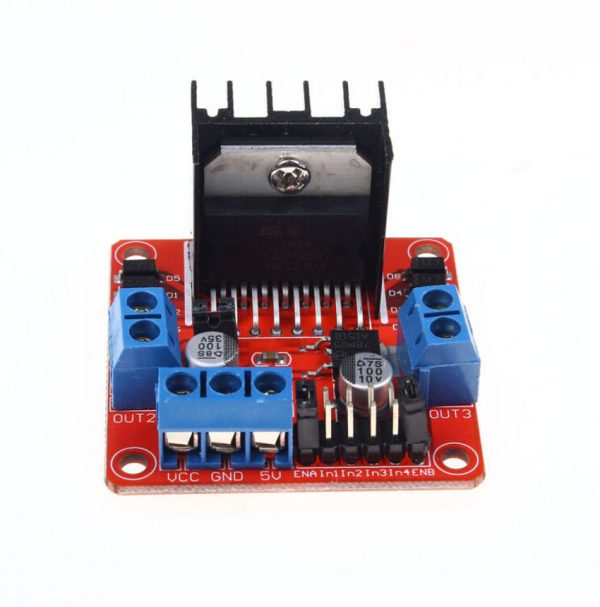
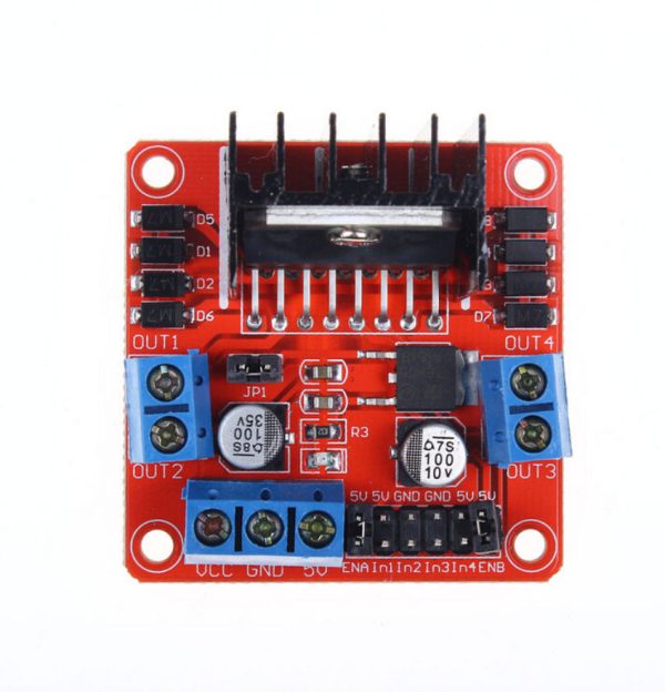
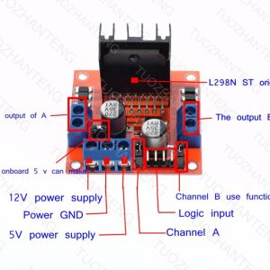
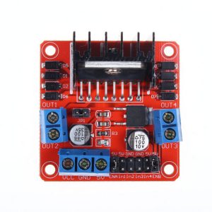
🔌 Pinout (Typical L298N Module)

Power

Terminal Function
+12V / Vmotor Motor supply input
GND Ground
+5V 5V output (if regulator enabled) OR 5V input

Motor Outputs

Terminal Function
OUT1/OUT2 Motor A
OUT3/OUT4 Motor B

Control Pins

Pin Function
ENA Enable Motor A (PWM for speed)
IN1/IN2 Direction Motor A
IN3/IN4 Direction Motor B
ENB Enable Motor B (PWM for speed)

📌 Many boards include jumpers on ENA/ENB. Remove jumper to use PWM.


⚠ Onboard 5V Regulator Jumper Note

Some L298N boards include a 5V regulator enable jumper:

  • If motor supply is high enough (often >7V), regulator can provide 5V output.

  • If you power Arduino separately, you can leave Arduino on USB and only share GND.

📌 If you are unsure, the safest approach:

  • Power motors from motor supply

  • Power Arduino separately

  • Share GND


🔌 Wiring – Arduino Uno (2 DC Motors)

L298N Arduino
ENA D5 (PWM)
IN1 D8
IN2 D9
IN3 D10
IN4 D11
ENB D6 (PWM)
GND GND

Motor supply → L298N Vmotor + GND
Motors → OUT1/OUT2 and OUT3/OUT4


🧪 1️⃣ DC Motor Direction Example (Motor A)

int ENA = 5;
int IN1 = 8;
int IN2 = 9;

void setup() {
pinMode(ENA, OUTPUT);
pinMode(IN1, OUTPUT);
pinMode(IN2, OUTPUT);
}

void loop() {
// Forward
digitalWrite(IN1, HIGH);
digitalWrite(IN2, LOW);
analogWrite(ENA, 200); // speed 0-255
delay(2000);

// Stop
analogWrite(ENA, 0);
delay(1000);

// Reverse
digitalWrite(IN1, LOW);
digitalWrite(IN2, HIGH);
analogWrite(ENA, 200);
delay(2000);

// Stop
analogWrite(ENA, 0);
delay(1000);
}


🧪 2️⃣ Two Motor Robot Example (Tank Drive)

int ENA = 5, IN1 = 8, IN2 = 9;
int ENB = 6, IN3 = 10, IN4 = 11;

void setup() {
pinMode(ENA, OUTPUT); pinMode(IN1, OUTPUT); pinMode(IN2, OUTPUT);
pinMode(ENB, OUTPUT); pinMode(IN3, OUTPUT); pinMode(IN4, OUTPUT);
}

void motorA(int speed) { // -255 to +255
if (speed >= 0) { digitalWrite(IN1, HIGH); digitalWrite(IN2, LOW); }
else { digitalWrite(IN1, LOW); digitalWrite(IN2, HIGH); speed = -speed; }
analogWrite(ENA, constrain(speed, 0, 255));
}

void motorB(int speed) {
if (speed >= 0) { digitalWrite(IN3, HIGH); digitalWrite(IN4, LOW); }
else { digitalWrite(IN3, LOW); digitalWrite(IN4, HIGH); speed = -speed; }
analogWrite(ENB, constrain(speed, 0, 255));
}

void loop() {
motorA(200); motorB(200); delay(2000); // forward
motorA(-200); motorB(-200); delay(2000); // reverse
motorA(200); motorB(-200); delay(1500); // spin
motorA(0); motorB(0); delay(1000); // stop
}


🧪 3️⃣ Stepper Motor Example (Basic 4-Wire Bipolar)

You can drive a small bipolar stepper using OUT1–OUT4.
This is a basic full-step sequence (not microstepping).

int IN1 = 8, IN2 = 9, IN3 = 10, IN4 = 11;

void setup() {
pinMode(IN1, OUTPUT); pinMode(IN2, OUTPUT);
pinMode(IN3, OUTPUT); pinMode(IN4, OUTPUT);
}

void stepMotor(int step) {
switch (step) {
case 0: digitalWrite(IN1,HIGH); digitalWrite(IN2,LOW);
digitalWrite(IN3,HIGH); digitalWrite(IN4,LOW); break;
case 1: digitalWrite(IN1,LOW); digitalWrite(IN2,HIGH);
digitalWrite(IN3,HIGH); digitalWrite(IN4,LOW); break;
case 2: digitalWrite(IN1,LOW); digitalWrite(IN2,HIGH);
digitalWrite(IN3,LOW); digitalWrite(IN4,HIGH); break;
case 3: digitalWrite(IN1,HIGH); digitalWrite(IN2,LOW);
digitalWrite(IN3,LOW); digitalWrite(IN4,HIGH); break;
}
}

void loop() {
for (int i = 0; i < 4; i++) {
stepMotor(i);
delay(5);
}
}

📌 For serious stepper projects (CNC/3D printing), use A4988 / DRV8825 / TMC drivers.


🔋 Power & Noise Tips

  • Use an external supply sized for your motors

  • Add a capacitor across motor supply near the board (e.g. 470µF–1000µF)

  • Keep motor wires short where possible

  • Provide airflow if running near max load


🧠 Common Issues & Fixes

Issue Cause Fix
Motors weak Voltage drop Increase supply voltage (within motor spec)
Board very hot Load too high Reduce load / add airflow / use better driver
Arduino resets Power sag/noise Separate motor supply + common GND
No speed control EN jumpers installed Remove ENA/ENB jumpers for PWM
Wrong direction Motor wires swapped Swap motor leads or invert IN pins

Additional information

Weight 30 g
Dimensions 260 × 160 × 20 mm

Reviews

There are no reviews yet.


Only logged in customers who have purchased this product may leave a review.