
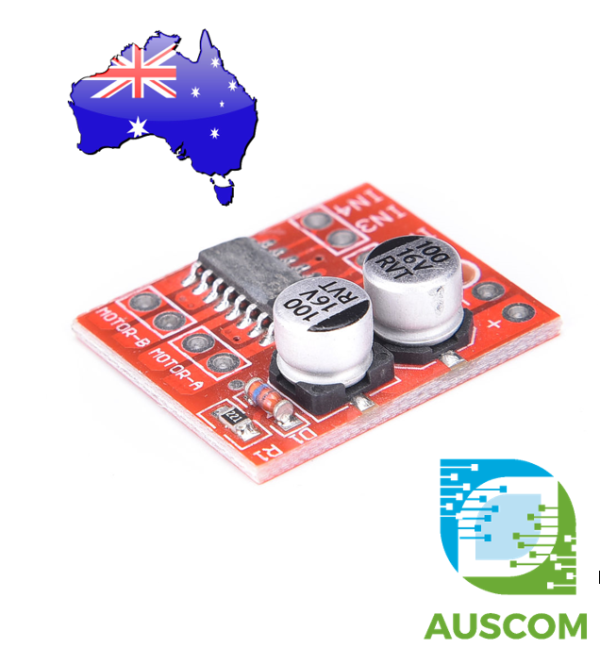
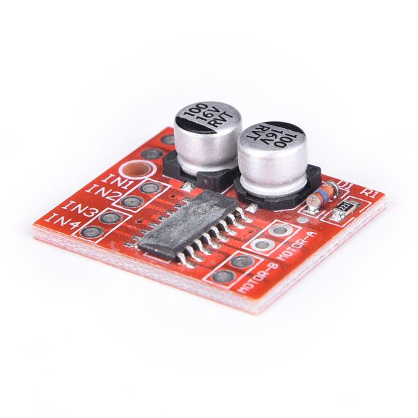
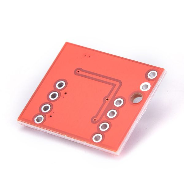
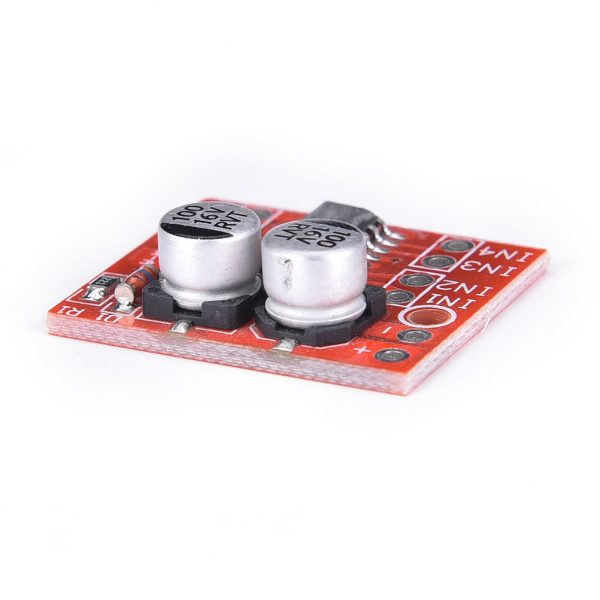
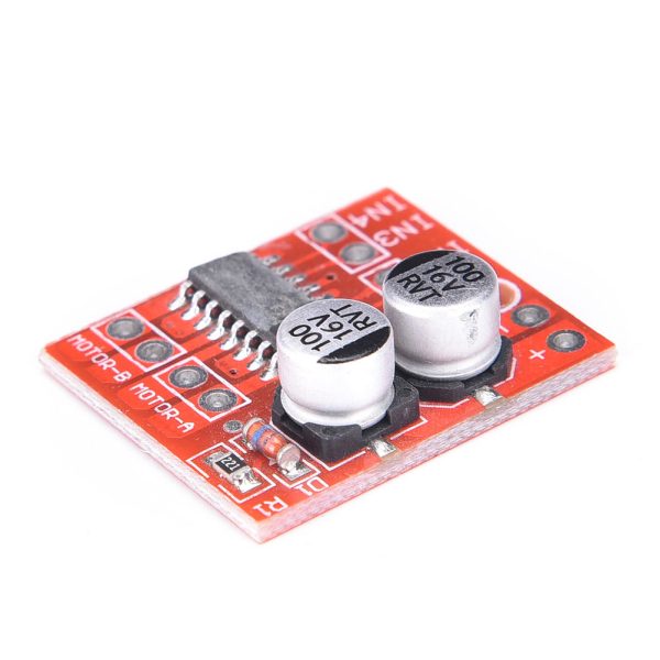
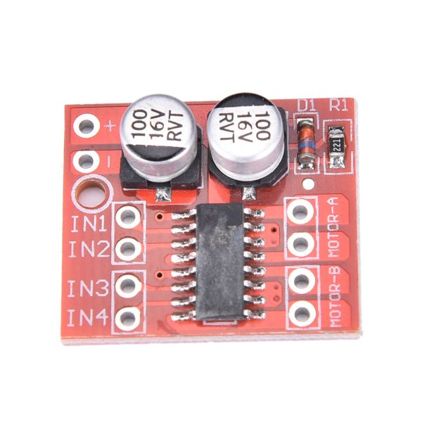
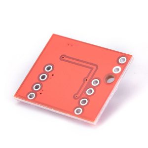
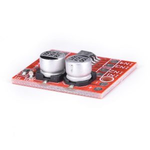
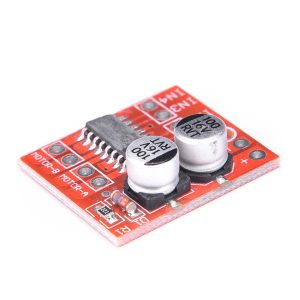
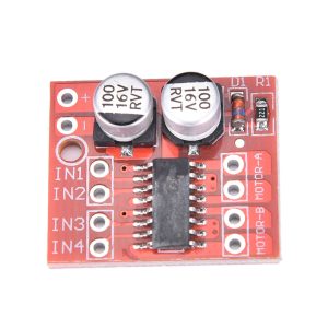
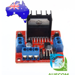
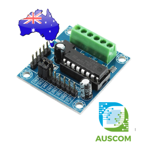
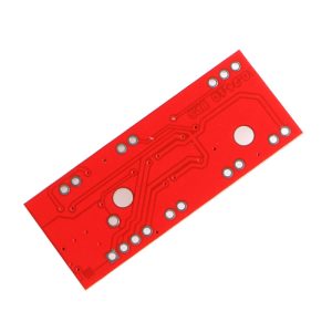
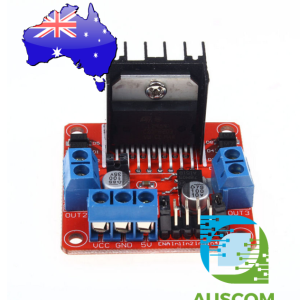
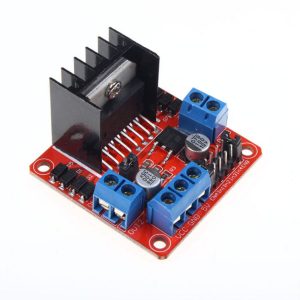
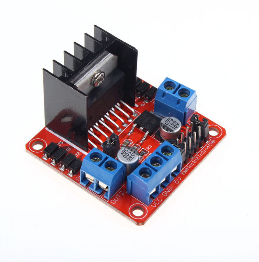
Mini L298N 1.5A Dual Channel DC Stepper Motor Driver Module PWM Speed Control
$8.50 Inc. GST
You save (%)
- Description
- Code Examples
- Additional information
- Reviews (0)
Description
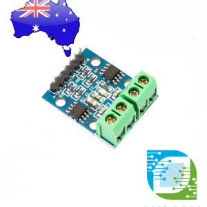
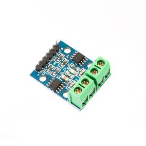
Enhance your Projects with the Mini L298N 1.5A Dual Channel DC Stepper Motor Driver Module
Unlock the potential of your battery-powered smart cars, toy vehicles, and robots with our Mini L298N Motor Driver Module. Designed to elevate your creations, this module offers precise control, efficient performance, and seamless integration. Whether you’re a hobbyist or an engineer, our motor driver module is a must-have addition to your toolkit.
Key Features:
- Advanced Motor Control: This module is a powerhouse for your projects, capable of driving two DC motors or a 4-wire 2-phase stepper motor. Achieve both forward and reverse rotations with the added benefit of adjustable rotation speeds.
- Optimal Performance: Equipped with imported original chips and low on-resistance MOS switches, this module guarantees minimal heat generation, eliminating the need for a bulky heat sink. This results in smaller dimensions and lower power consumption, making it perfect for battery-powered applications.
- Robust Protection: Our module offers dual 1.5A outputs, peaking at 2.5A, ensuring uninterrupted performance even in demanding scenarios. The built-in thermal protection circuit prevents motor stalls from causing damage, automatically recovering after temperature normalization.
- Compact Design: With its ultra-compact dimensions of 24.7mm length, 21mm width, and 5mm height, and 2mm mounting hole diameter, this module seamlessly fits into your projects without adding unnecessary bulk.
Product Specifications:
- Dual H-bridge motor driver supports two DC motors or a 4-wire two-phase stepper motor.
- Module supply voltage ranges from 2V to 10V, accommodating a variety of power sources.
- Signal input voltage spans 1.8V to 7V, ensuring compatibility with various control systems.
- Single operating current at 1.5A, with peak current capabilities reaching 2.5A. Impressively low standby current of less than 0.1uA.
- Built-in common conduction circuit prevents motor malfunction when input pins are left unconnected.
- Integrated thermal protection circuit with hysteresis effects (TSD), ensuring worry-free operation even in challenging conditions.
Precautions:
- Polarity Protection: Ensure proper power connection to prevent circuit damage due to reversed polarity.
- Safe Operations: In case of output short to ground or motor stall, the module incorporates heat protection. However, extreme conditions like voltages exceeding 10V or peak currents beyond 2.5A can still pose risks.
Elevate your projects today with the Mini L298N Motor Driver Module. Unleash its potential in your battery-powered vehicles, robotics experiments, and beyond. Order now and experience precision, efficiency, and control like never before.
Package Includes:
- 1 x Mini L298N 1.5A Dual Channel DC Stepper Motor Driver Module
📌 Code Examples & Usage – Mini L298N 1.5A Dual Motor Driver Module
📋 Overview
This Mini L298N 1.5A dual channel motor driver module is a compact H-bridge driver designed for controlling:
-
2 × small DC motors
-
1 × small bipolar stepper motor
It’s suitable for low-to-moderate current applications such as robot cars, small actuators, conveyors, and educational robotics, and works with Arduino, ESP32, ESP8266, Raspberry Pi, and PLC digital outputs.
⚙ Key Features
-
Dual H-bridge outputs
-
Rated current: ~1.5A per channel
-
Motor voltage: ~5–24V DC (depending on module specs)
-
Logic interface: 3.3V – 5V compatible
-
PWM speed control plus direction control
📌 More efficient and smaller than classic full-size L298N modules.
⚠ IMPORTANT – Power & Current Notes
🚨 Continuous current limited (~1.5A)
✔ Good for small DC motors (TT, micro gear motors)
✔ OK for small stepper motors with low current draws
❌ Not suitable for:
-
Large steppers (e.g., NEMA 17 at rated currents)
-
High-torque DC motors drawing >1.5A
-
Long or continuous heavy loads without heatsinking
📌 If you need higher current or efficiency, consider:
-
TB6612FNG (better efficiency)
-
BTS7960 / MOSFET-based drivers
🔌 Pinout & Connections
Most mini L298N modules provide:
| Pin | Function |
|---|---|
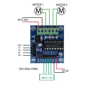
| EN A | PWM speed control Motor A |
| IN1 / IN2 | Direction Motor A |
| EN B | PWM speed control Motor B |
| IN3 / IN4 | Direction Motor B |
| VM | Motor supply (5–24V DC) |
| GND | Ground |
| VCC (optional) | Logic supply (5V) |
| Motor A | OUT1 / OUT2 |
| Motor B | OUT3 / OUT4 |
📌 Logic VCC often comes from your microcontroller’s 5V.
🔌 Power Setup
-
Motor supply (VM): 5–24V DC (motor dependent)
-
Logic supply: 5V (microcontroller)
-
Common ground: Motor supply and logic ground must be tied
⚠ If your module has a 5V regulator jumper, follow the module’s markings — if not, use a separate 5V logic supply.
🔌 Wiring – Arduino Uno
| Mini L298N | Arduino |
|---|---|
| EN A | D5 (PWM) |
| IN1 | D8 |
| IN2 | D9 |
| EN B | D6 (PWM) |
| IN3 | D10 |
| IN4 | D11 |
| VM | Motor power (5–12V) |
| GND | Shared ground |
🧪 1️⃣ DC Motor – Direction & Speed Example
🧪 2️⃣ PWM Speed Control (Independent)
🧪 3️⃣ Bipolar Stepper Motor – Basic Sequence
You can drive a small 4-wire bipolar stepper by using both H-bridges:
📌 For serious stepper control, consider drivers with microstepping.
🔋 Power & Heat Notes
✔ Use a separate motor supply sized to your motor voltage
✔ Shared ground is required
✔ Expect some heat at higher loads — consider airflow
✔ Keep motor wires short
🧠 Common Issues & Fixes
| Issue | Cause | Fix |
|---|---|---|
| Motor not turning | Wiring error | Swap motor leads |
| Weak torque | Low voltage | Increase supply within spec |
| Driver overheats | High current | Use TB6612 / MOSFET drivers |
| Arduino resets | Noise | Separate supplies & GND tie |
Additional information
| Weight | 20 g |
|---|---|
| Dimensions | 260 × 160 × 20 mm |
Only logged in customers who have purchased this product may leave a review.














Reviews
There are no reviews yet.