


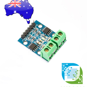
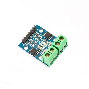


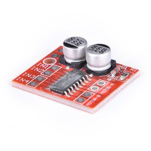
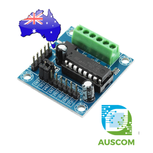
L9110S H-bridge Stepper Motor Dual DC Motor Driver Controller Module Arduino

$6.50 Inc. GST
You save
Wiring, Arduino code and troubleshooting for the L9110S dual H-bridge motor driver module. Covers two brushed DC motors, PWM speed and direction control, external…
Model: L9110S- Description
- Code Exmaples
- Additional information
- Reviews (0)
Description
🔧 L9110S Dual DC Motor Driver Module 2.5–12V H-Bridge | AuscomTech
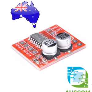
The L9110S is a compact dual-channel motor drive board designed for controlling small DC motors and 4-wire 2-phase stepper motors from microcontroller GPIO signals.
Its dual H-bridge outputs allow independent forward and reverse control of two DC motors, while the four control inputs provide simple digital direction switching.
The small 28 × 21 mm PCB is well suited to robotics, compact automation projects, educational electronics and embedded motor-control systems.
⭐ Key Features
- Dual Motor Control – drives two DC motors independently from separate control inputs.
- Stepper Motor Support – suitable for controlling a 4-wire 2-phase stepping motor.
- Wide Supply Range – operates from DC 2.5 V to 12 V.
- Bidirectional Operation – H-bridge outputs provide forward and reverse motor direction control.
- Microcontroller Interface – AIA, AIB, BIA and BIB inputs connect to external controller I/O signals.
- Power Indicator – onboard indicator shows when module power is applied.
- Compact PCB – approximately 28 × 21 mm for space-limited projects.
- Mounting Holes – includes 3 mm mounting holes for secure installation.
📊 Technical Specifications
- Driver IC: L9110S
- Supply Voltage: DC 2.5–12 V
- Maximum Operating Current: 0.8 A
- Motor Channels: 2
- Supported Loads: 2 × DC motors or 1 × 4-wire 2-phase stepper motor
- Control Inputs: AIA, AIB, BIA, BIB
- Motor Outputs: OA1, OB1, OA2, OB2
- Power Connections: VCC and GND
- PCB Size: approximately 28 × 21 mm
- Mounting Hole Diameter: 3 mm
🧩 Typical Applications
- Small DC motor control
- 4-wire 2-phase stepper motor projects
- Robotics and smart car projects
- Embedded automation systems
- Microcontroller-controlled mechanisms
- Educational electronics projects
⚠️ Important Notes
- Motor operating voltage must remain within the DC 2.5–12 V module supply range.
- Maximum operating current is specified as 0.8 A.
- AIA high with AIB low drives channel A in one direction; reversing the logic reverses the motor direction.
- BIA high with BIB low drives channel B in one direction; reversing the logic reverses the motor direction.
- OA1/OB1 and OA2/OB2 are the two motor output pairs.
- Check motor voltage and current requirements before connecting power.
📦 Package Includes
- 1 × L9110S Dual Motor Driver Module
🔗 Recommended Accessories (Not Included)
- Microcontroller development board – provides GPIO control signals
- DC 2.5–12 V power supply – powers the driver and connected motor
- Jumper wires – connects the control and power pins
- DC motor or 4-wire 2-phase stepper motor – compatible motor load
📌 Code Examples & Usage – L9110S Dual DC / Stepper Motor Driver Module
📋 Overview
The L9110S motor driver module is a compact dual H-bridge driver designed to control two DC motors or one small bipolar stepper motor. It is ideal for low-voltage, low-current motor control projects using Arduino, ESP32, ESP8266, and Raspberry Pi.
Common applications include:
-
Small robot cars
-
Line-following robots
-
Fan and pump control
-
Educational motor control projects
-
Lightweight stepper motor experiments
⚙ Key Features
-
Driver IC: L9110S
-
Motor channels: 2 (A & B)
-
Motor voltage: 5–12V DC (typical)
-
Control method: Logic-level IN pins
-
Can drive:
-
2 × DC motors
-
1 × small bipolar stepper motor
-
-
Simple wiring and low component count
⚠ IMPORTANT – Motor Limitations
🚨 This module is NOT suitable for high-current motors.
✔ Best for:
-
Small DC motors (TT motors, gear motors)
-
Small 4-wire bipolar steppers
❌ Not suitable for:
-
NEMA 17+ steppers
-
High-torque motors
-
CNC or 3D printer motors
📌 Typical current capability is ~800 mA peak (much lower continuous).
🔌 Pinout
Most L9110S boards expose:
| Pin | Function |
|---|---|
| A-1A | Motor A input 1 |
| A-1B | Motor A input 2 |
| B-1A | Motor B input 1 |
| B-1B | Motor B input 2 |
| VCC | Motor & logic supply |
| GND | Ground |
📌 Logic and motor supply are usually shared.
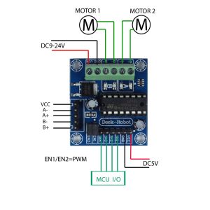
🔌 Wiring – DC Motor Example
Motor A
-
Motor wires → Motor A terminals
-
Control pins → A-1A, A-1B
Motor B
-
Motor wires → Motor B terminals
-
Control pins → B-1A, B-1B
🔌 Wiring – Arduino Uno Example (DC Motor)
| L9110S | Arduino |
|---|---|
| A-1A | D5 |
| A-1B | D6 |
| B-1A | D9 |
| B-1B | D10 |
| VCC | 6–9V motor supply |
| GND | GND |
📌 Arduino GND must be common with motor supply GND.
🧪 1️⃣ DC Motor Direction Control Example
🧪 2️⃣ Speed Control Using PWM
You can use PWM on one pin while holding the other LOW.
📌 Works on Arduino PWM-capable pins.
🧪 3️⃣ Bipolar Stepper Motor Example (4-Wire)
The L9110S can drive a small bipolar stepper motor using both channels.
Step Sequence (Full Step)
📌 Suitable for small steppers only (e.g. 28BYJ-48 converted to bipolar).
🔋 Power Notes
✔ Use a motor supply matched to the motor rating
✔ Start at the lowest safe voltage
✔ Avoid powering motors directly from Arduino 5V
✔ Expect noise — keep motor wiring short
🧠 Common Issues & Fixes
| Issue | Cause | Fix |
|---|---|---|
| Motor doesn’t move | Wiring error | Swap motor leads |
| Weak torque | Low supply voltage | Increase motor voltage |
| Arduino resets | Motor noise | Use external supply |
| Overheating | Motor too large | Use proper driver (L298N / TB6612 / A4988) |
| Stepper vibrates | Wrong sequence | Check step order |
Additional information
| Weight | 20 g |
|---|---|
| Dimensions | 260 × 160 × 20 mm |
Only logged in customers who have purchased this product may leave a review.








Reviews
There are no reviews yet.