
PCA9685 16 Channel 12-bit PWM Servo motor Driver I2C Module Arduino Robot WC

$11.40 Inc. GST
You save
- Description
- Code Examples
- Additional information
- Reviews (0)
Description
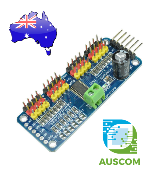
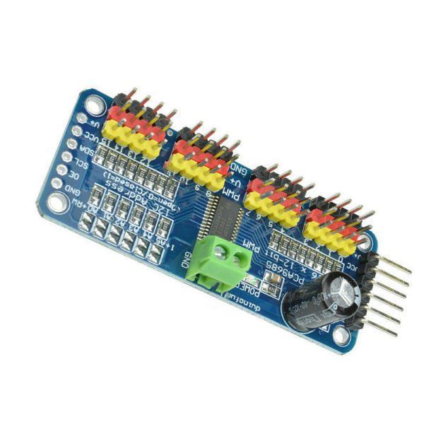
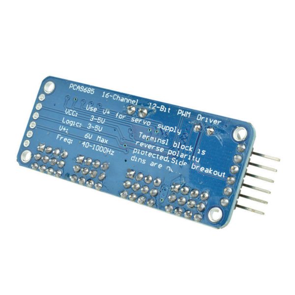
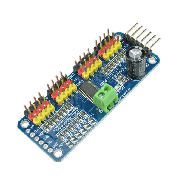
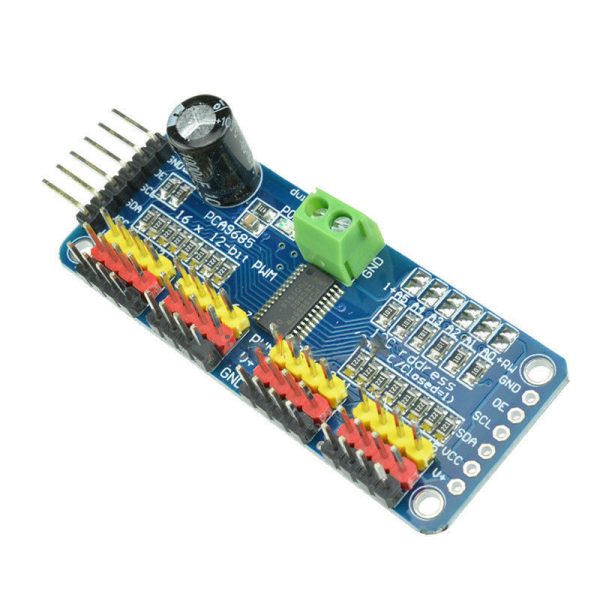
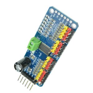
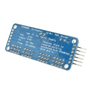
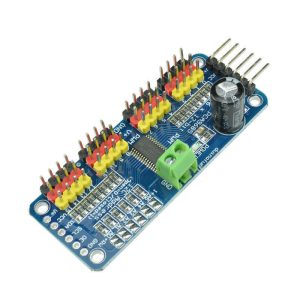
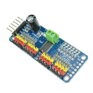
Enhance your project’s control capabilities with the PCA9685 16-Channel 12-Bit I2C PWM Servo Motor Driver Module for Arduino. This innovative module is a game-changer when your microcontroller faces a shortage of PWM output pins. Whether you’re crafting a dynamic robot, a versatile hexapod walker, or orchestrating a symphony of LEDs, this module delivers precise PWM control that empowers your creations.
Simplify your setup using just two pins to command 16 independent PWM outputs that run autonomously. Marvel at the potential of daisy-chaining up to 62 modules, giving you control over a staggering 992 PWM outputs. With seamless I2C communication between your microcontroller and the PCA9685, you gain the ability to command multiple servos in perfect harmony.
Key Features:
- Effortless Control: Seamlessly manage PWM with the built-in clock, liberating your microcontroller from continuous signaling and ensuring unhindered operation.
- Voltage Versatility: Operate comfortably at 5V compliance, allowing safe handling of up to 6V outputs even with a 3.3V microcontroller. This is ideal for illuminating LEDs with 3.4+ forward voltages, such as white or blue LEDs.
- Expanded Scalability: Employ the power of 6 address select pins, enabling you to integrate up to 62 modules on a single I2C bus. Unleash an impressive array of 992 outputs at your command.
- Customizable PWM: Tailor the PWM frequency, flexing up to approximately 1.6 KHz for your specific application.
- Pinpoint Precision: Leverage the 12-bit resolution for each output. For servo applications, relish the 4us resolution at a 60Hz update rate.
- Output Flexibility: Configure outputs as push-pull or open-drain, adapting to your project’s requirements.
- Swift Control: Utilize the output enable pin to swiftly disable all outputs, streamlining operations.
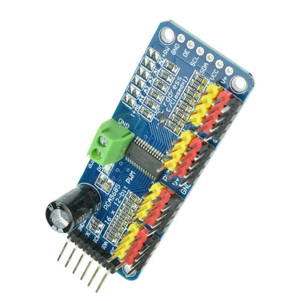
- Power Input Options: Benefit from the terminal block for power input, or conveniently use the 0.1″ breakout pins on the module’s side.
- Built-In Protection: Rest easy with reverse polarity protection on the terminal block input, safeguarding your module.
- Visual Confirmation: The vivid green power-on LED provides an instant status indicator.
- Efficient Connectivity: Utilize the organized 3-pin connectors, grouped in sets of 4, allowing you to effortlessly connect 16 servos concurrently.
- Seamless Expansion: Embrace the chainable design for effortless expansion to meet your project’s evolving needs.
- Output Safety: Equipped with 220 Ohm series resistors on all output lines, guaranteeing protection and simplifying LED driving.
- User-Defined Configuration: Employ solder jumpers for the 6 address select pins, customizing your module’s behaviour.
- Ready for Action: Receive a fully assembled and tested module, saving you time and effort.
Package Contents:
- 1 x PCA9685 16 Channel 12-Bit PWM Servo Motor Driver I2C Module
Elevate your project’s potential with the PCA9685 16-Channel 12-Bit I2C PWM Servo Motor Driver Module for Arduino. Unlock unprecedented control and precision, transforming your creations into remarkable feats of engineering.
📌 Code Examples & Usage – PCA9685 16-Channel PWM/Servo Driver Module (I²C)
📋 Overview
The PCA9685 is a 16-channel, 12-bit PWM driver that interfaces over I²C, making it perfect for controlling:
-
Multiple servos (up to 16)
-
LED brightness and RGB strips
-
DC motor drivers (PWM inputs)
-
Stepper motor drivers (PWM-based control)
-
Actuators and solenoids (via appropriate drivers)
It dramatically reduces the number of microcontroller pins needed and is ideal for Arduino, ESP32, Raspberry Pi, and other microcontroller / SBC platforms.
⚙ Key Features
-
16 individual PWM outputs
-
12-bit resolution (4096 steps)
-
Communicates via I²C
-
Up to 1.6 kHz PWM frequency
-
Can be chained (multiple boards on the same bus)
-
Standard logic: 3.3V / 5V compatible
⚠ IMPORTANT – Power Notes
✔ Servos should be powered from a separate 5–6V supply
✔ Do not power servos from the board’s logic supply
✔ Always share ground between servo supply and controller
Most common mistake:
Powering servos from Arduino 5V → resets / browns out
🔌 Pinout & Connections
| Pin | Function |
|---|---|
| VCC | Logic power (3.3V–5V) |
| GND | Ground |
| SDA | I²C data |
| SCL | I²C clock |
| OE | Output enable (active LOW) |
| V+ | External servo/motor power (5–6V) |
📌 Most modules include a screw terminal for V+ and GND.
🔌 Wiring – Arduino / ESP32
Logic (I²C)
| PCA9685 | Arduino |
|---|---|
| VCC | 5V |
| GND | GND |
| SDA | A4 (Uno/Nano) / GPIO21 (ESP32) |
| SCL | A5 (Uno/Nano) / GPIO22 (ESP32) |
Servo Power
| Servo | External 5–6V supply |
|---|---|
| V+ | 5–6V |
| GND | Shared ground |
| Signal | PCA9685 channel pin |
📌 Always tie the servo supply ground to the Arduino/ESP32 ground.
🛠 Arduino IDE Library Setup
Install via Library Manager:
-
Adafruit PWM Servo Driver Library
-
Dependency: Adafruit BusIO
Arduino IDE → Sketch → Include Library → Manage Libraries → search “PCA9685”.
🧪 1️⃣ Basic PWM Control Example
This simple sketch dims PWM channel 0 from 0→4095 and back.
🧪 2️⃣ Control a Servo (Angles)
Servos are controlled by PWM pulse width, typically:
-
~500 µs → 0°
-
~1500 µs → 90°
-
~2500 µs → 180°
Using a 50 Hz refresh rate (~20 ms):
📌 Adjust servoMin and servoMax to match your physical servo.
🎛 Microstepping & Frequency Notes
-
Higher PWM frequencies (e.g. 500–1000 Hz) are ideal for LED brightness
-
Lower frequencies (e.g. 50–100 Hz) are ideal for servos
-
You can drive motors / drivers by adjusting frequency & duty cycle
🔢 Multiple Boards on One Bus
The PCA9685 allows different addresses via address pins (A0–A5).
To address multiple boards:
This lets you scale up to hundreds of PWM channels on a single I²C bus.
🧠 Common Issues & Fixes
| Issue | Cause | Fix |
|---|---|---|
| Servos twitch | Power sag | Use separate 5V supply |
| No I²C found | Wrong wiring | Swap SDA/SCL |
| Strange PWM | No ground common | Tie grounds together |
| Unresponsive | No library | Install Adafruit PCA9685 |
Additional information
| Weight | 40 g |
|---|---|
| Dimensions | 260 × 160 × 20 mm |
Only logged in customers who have purchased this product may leave a review.












Reviews
There are no reviews yet.