
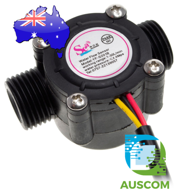

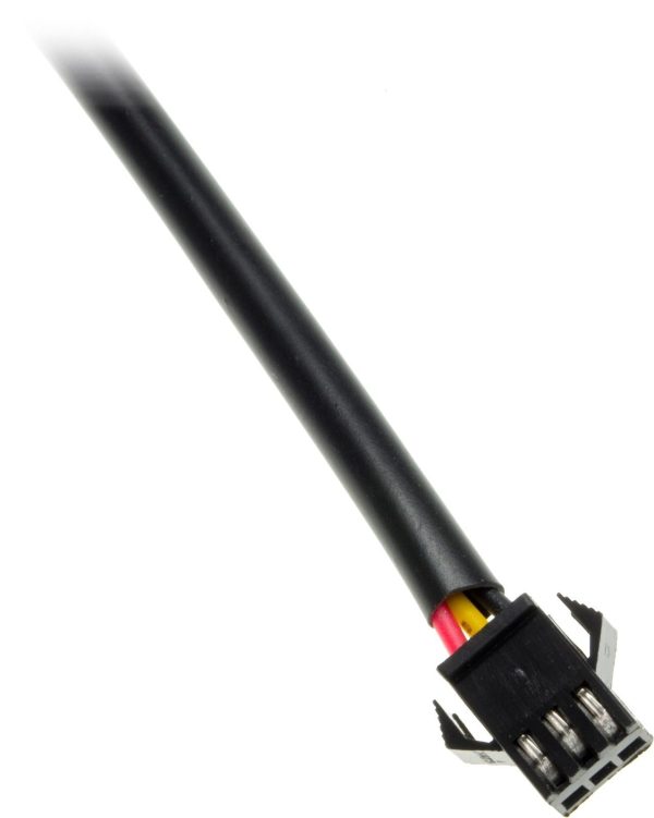
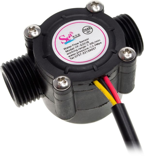
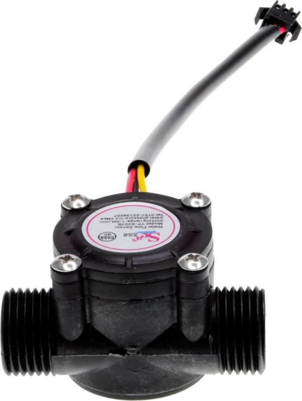
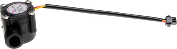
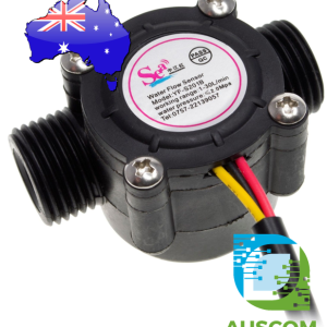
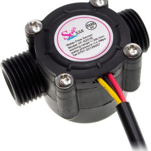
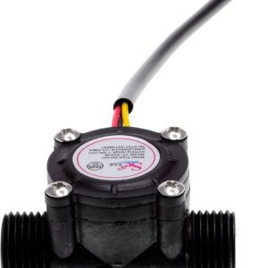
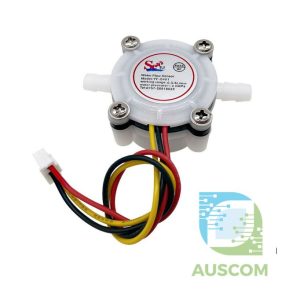
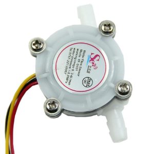
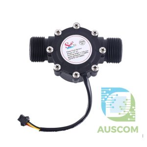
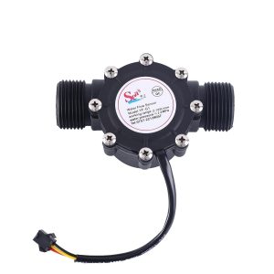
Sea YF-S201 Flowmeter G1/2″ Hall Effect Water Flow Sensor 1-30lpm
$14.95 Inc. GST
You save
- Description
- Code Examples
- Additional information
- Reviews (0)
Description
Introducing the Sea YF-S201 Flowmeter G1/2″ Hall Effect Water Flow Sensor – your indispensable tool for precisely measuring the flow rate of water and other non-flammable liquids. Whether you’re an Arduino enthusiast, microcontroller hobbyist, or in need of accurate flow measurements for gases (with density adjustments), this flowmeter, equipped with G1/2 threads, stands as your dependable solution.
Key Features:
- G1/2 Threaded Design: Seamlessly integrate this flowmeter into your setup for effective capture of flow rates.
- Hall Effect Sensor Interface: Experience precise measurements and consistent data output.
- Versatile Performance: Suited for various applications, offering a capacity range of 1-30L/min and withstanding pressures up to 1.75 MPa.
- Stainless Steel Axis: Built to endure, the stainless steel axis ensures durability and longevity.
Technical Specifications:
- Minimum Rated Working Voltage: DC4.5 5V-24V
- Maximum Operating Current: 15 mA (DC 5V)
- Working Voltage Range: DC 5~18V
- Load Capacity: ≤ 10mA (DC 5V)
- Operating Temperature: -25 ~ 80°C
- Operating Humidity Range: 35% ~ 90% RH (non-frost conditions)
- Pressure Tolerance: 1.75 Mpa
- Thread Size: 1/2″
- Signal Amplitude – High: ≥ 4.6V
- Signal Amplitude – Low: ≤ 0.5V
- Electric Strength: 1250V/min
- Insulation Resistance: ≥ 100MΩ
- Hydrostatic Pressure Testing: ≤ 2.0Mpa
- Error Margin: ±5%
- Flow-Pulse Rates: 2L/min=16Hz, 4L/min=32.5Hz, 6L/min=49.3Hz, 8L/min=65.5Hz, 10L/min=82Hz
Experience precision and efficiency with the YF-S201 Flowmeter G1/2″ Hall Effect Water Flow Sensor. Ideal for DIY electronics projects or industrial needs, this sensor ensures reliable performance and durability. Unlock streamlined flow measurement processes with its versatile features and technical prowess. Order now for a compact package delivering accuracy and efficiency in one.
📌 Code Examples & Usage – YF-S201 Hall Effect Water Flow Sensor (G1/2″)
📋 Overview
The YF-S201 water flow sensor is a compact Hall-effect pulse output flow meter designed for measuring liquid flow rate and total volume. It produces a digital pulse signal proportional to the flow rate, making it ideal for:
-
Water flow monitoring
-
Pump control & protection
-
DIY irrigation systems
-
Industrial prototypes
-
Arduino, ESP32, ESP8266 & PLC pulse inputs
This model features G1/2″ threaded ports and is suitable for 1–30 L/min flow rates.
⚙ Key Features
-
Sensor type: Hall effect flow sensor
-
Model: YF-S201
-
Pipe size: G1/2″
-
Flow range: 1–30 L/min
-
Output: Pulse (open collector / TTL compatible)
-
Supply voltage: 5–18 VDC
-
Suitable for water and compatible liquids
-
Low pressure loss
⚠ IMPORTANT – Output Signal Type
🚨 The YF-S201 outputs a pulse signal, NOT analog voltage.
-
Each pulse represents a fixed fraction of flow
-
Flow rate is calculated from pulse frequency
-
Total volume is calculated by counting pulses
✔ Works well with:
-
Microcontroller interrupt pins
-
PLC high-speed counter (HSC) inputs
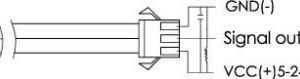
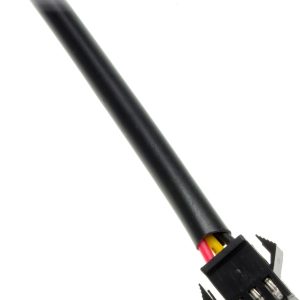
🔌 Wiring
Typical Wire Colours (may vary by batch)
| Wire | Function |
|---|---|
| Red | VCC (5–18 V) |
| Black | GND |
| Yellow | Pulse signal |
📌 If colours differ, follow the marking on the cable or datasheet.
🔌 Wiring – Arduino / ESP32
| Sensor | Arduino / ESP32 |
|---|---|
| Red | 5V |
| Black | GND |
| Yellow | Digital input (interrupt pin) |
📌 Use an interrupt-capable pin for best accuracy.
🧪 Pulse Characteristics (Calibration)
For the YF-S201, a commonly used calibration factor is:
Equivalent forms:
-
≈450 pulses per litre
-
≈7.5 pulses per second per L/min
⚠ Actual calibration may vary slightly between sensors and installations.
For accuracy-critical applications, perform a volume calibration.
🧪 Arduino Example – Flow Rate & Total Volume
🧪 ESP32 Notes
-
Use GPIOs that support interrupts
-
Use 3.3V logic (signal output is compatible)
-
If noise is present, add a 10k pull-up to 3.3V
📐 PLC Usage Notes
-
Use a high-speed counter (HSC) input
-
Supply sensor from 12–24V if required (check PLC IO specs)
-
Scale pulses in ladder logic or PLC math blocks
Example logic:
🧠 Installation Notes
✔ Install with arrow aligned to flow direction
✔ Avoid mounting directly after sharp bends
✔ Keep sensor full of liquid during operation
✔ Not suitable for dirty or particulate-heavy fluids
🧠 Common Issues & Fixes
| Issue | Cause | Fix |
|---|---|---|
| No pulses | Wiring error | Check signal & GND |
| Erratic readings | Turbulence | Add straight pipe run |
| Low flow not detected | Below minimum | Operate above 1 L/min |
| MCU resets | Noise | Add decoupling / pull-up |
Additional information
| Weight | 50 g |
|---|---|
| Dimensions | 40 × 60 × 35 mm |
Only logged in customers who have purchased this product may leave a review.












Reviews
There are no reviews yet.